One of the reasons I fell in love with the Stellaris Launchpad boards is that they are modularly  expandable. This notion is difficult to explain without comparison to STM Discovery boards, which have a row or two of pins on each side. The idea is simple: you hook one end of your wire to the right pin, and the other end to your breadboard, or you design a custom baseboard specific to the Discovery model. Stellaris takes this idea a little further. The layout of the pins is standardized, not just for the Stellaris, but across the family of TI development boards. Enter the Booster Packs: standardized add-on modules for TI boards. These modules are stackable, so it is possible to connect more than one to a single Stellaris board. This is why I wanted to use the Stellaris for this project. It’s much easier to build a booster pack than to tell people how to connect 32 wires; most people have problems connecting four of them to a buspirate. Let’s look at some of the design choices.
Constraints, constraints, constraints
It’s easy to imagine connecting a LPC chip: six wires and power. In reality, the situation is nowhere near as bright. Four ID pins need to be pulled low, reset pins (yes, there is more than one) need to be pulled high, and some pins simply cannot be left floating. Thus, even a simple bus like LPC becomes a nightmare. Without a logic analyzer to tell what works and what does not, the result is frustration and even self-inflicted injuries. Consequently, I wanted to do a few things right from the beginning(TM).
The most important point was to have all pins properly connected with zero wires. Users should not have to worry about what connects to where. Remember, these chips have 32 pins.
I also wanted to support all possible bus types. LPC and FWH are identical hardware-wise, and are not a problem to support concurrently. SPI is also just a few extra traces that lead to a header. On the other hand, having a programmer that also supports parallel mode is a much harder problem. It turns out there are really two “parallel” modes. The first one is ISA, where the chip is accessed via a linear address space. You put the address you want to access on the address pins, handle a couple of handshake lines to tell the chip if you want to read or write, and move the data over a separate 8-bit data bus.
On the other hand, the second “parallel” mode is a real pain. It uses a 2-dimensional address space, where you need to drive a row address, then a column address, and only then access the data. It’s called PP or “parallel programming” mode. Luckily we get a break: PP mode is an auxiliary programming mode specific to some LPC chips. If we support LPC, we don’t need PP. PP goes in the garbage bin (for now).
Now we need an efficient way to connect the GPIOs to the chip. By “efficient” I mean minimizing the number of GPIO accesses, and the number of bitshifts we need to do in firmware. A poorly chosen pinout will result in abysmal performance, as the 80MHz core struggles to shift the correct bit to the correct GPIO. My choice here was limited, as the best I could do was assign successive GPIOs to successive address pins. I spent the entire Sunday looking over chip datasheets and deciding on this “spaghetti recipe”.
Flexibility – a big issue
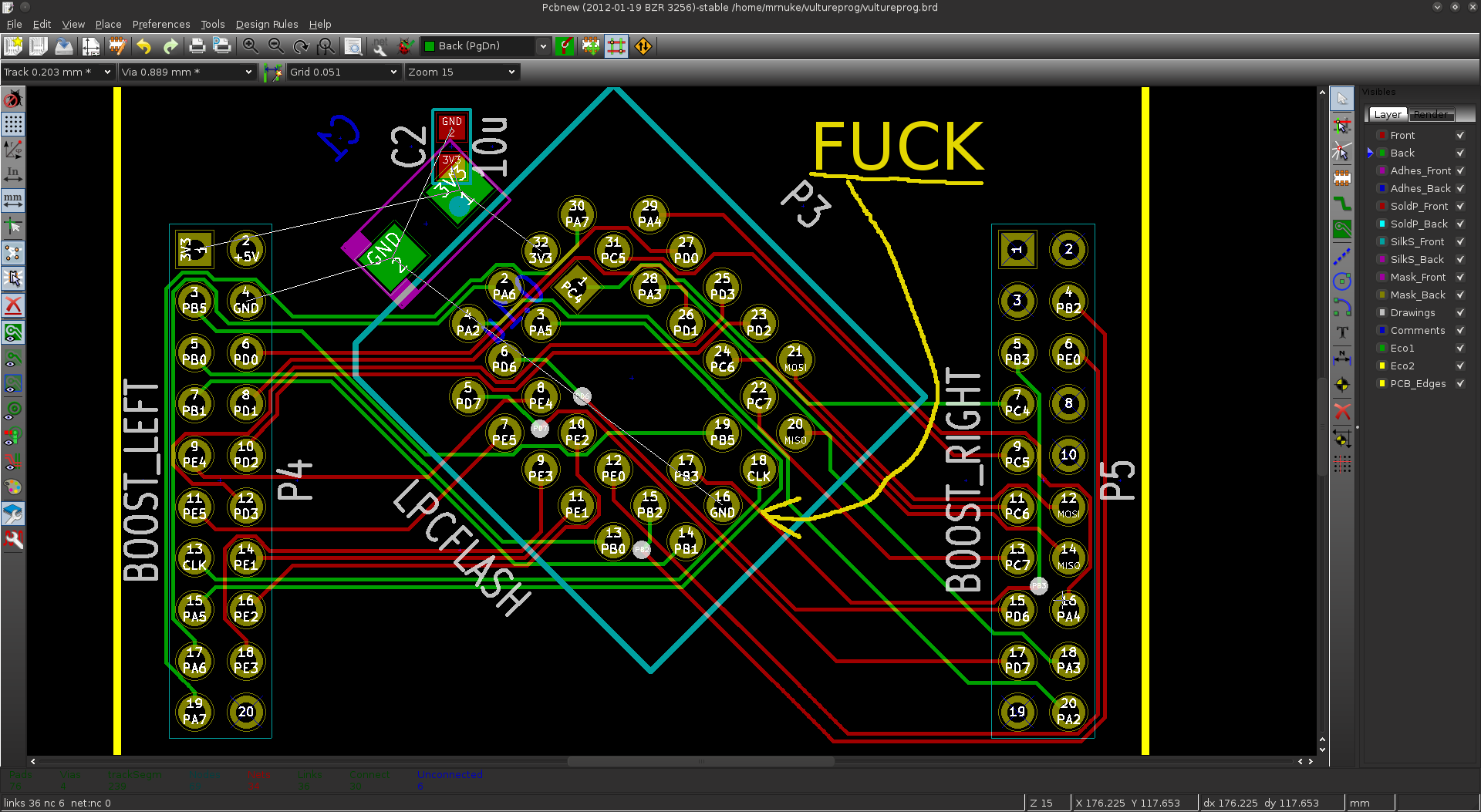
I also wanted to have the option between a normal PLCC32 socket, or a ZIF socket (AKA clamshell). I was really an idiot for thinking I would have both on the same board. On paper, it looks very straightforward. In reality, adjacent pins are on different hemispheres of the globe, and routing them is well, the tastiest spaghetti you have ever eaten. There was no way I could fit both a clamshell, and a PLCC32 socket. There was no way to route the 32 or so tracks on just 2 layers. So I killed the clamshell, the SPI header, and the LPC header. After a couple of hours of messing with the routing, I always had one or two pins that got cornered.
Even routing a simple PLCC socket proved difficult.
What coffee can do to you
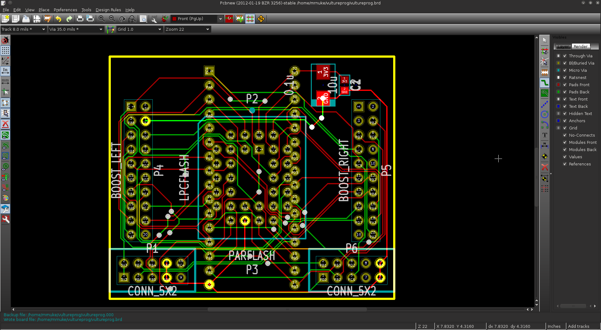
I decided to start over, with all the components in place. Once I reduced the track size to 8 mils, and spacing to 6 mils, I was able to route two tracks between a set of pins. This time, I placed the socket inside the clamshell, and managed to connect the two using just the top layer. I then worked from the booster pack connection to the DIP pins on the same side of the board, again, using only the top layer. Then I started using the bottom layer for DIP pins on the opposite side. After a few hours, Chuck Norris warped space and time to make room for all the tracks:
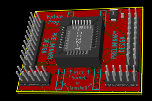
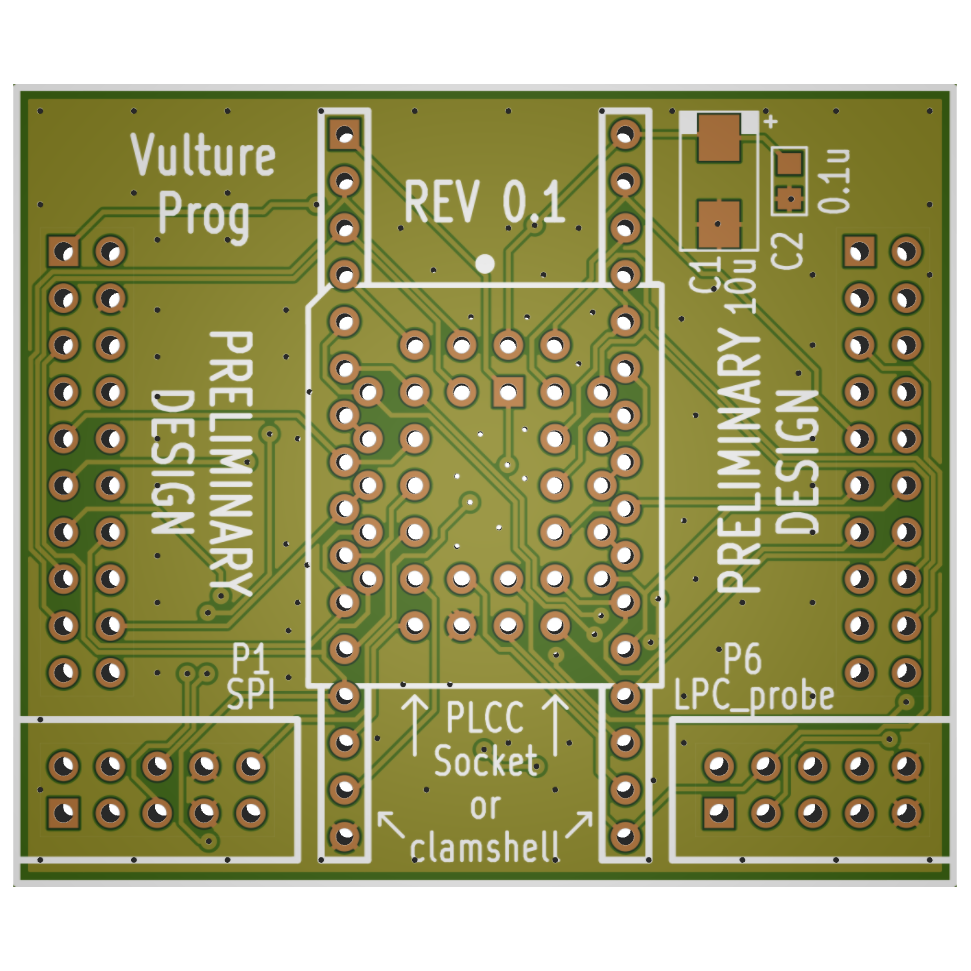
From here, it was a matter of optimizing the routing, taking care of ground planes and other finishing touches. In the end, we get VultureProg hardware version 0.1:
Don’t let the PRELIMINARY DESIGN warning fool you. There is an infinitesimal possibility I will ever want to go back and revise the design. We have 35 GPIOs. accessible on the Stellaris. Five of them are connected to the on-board LEDs and buttons. The remaining 30 are all used up.
Conclusion
If you are a Kicad user, you can head over to yet another one of my GitHub repositories. If you do not have a way to consume Kicad files, you can look in the doc and gerbers directories. Feel free to feed the gerbers to Mayhew Labs’ 3D Gerber Viewer (hint: you can rotate the board in 3D). With all that being done I ordered the first batch of PCBs from Seed Studio’s Fusion PCB service. Routing is definitely too crammed and painful, but I really wanted something versatile and flexible. Whether it lives up to its design goals in REV 0.1 or REV 0.2 remains to be seen. My money is on REV 0.1 — quite literally.


