Hello everyone! Coverity has come back online again after its long upgrade, and with it a pile of new scan issues (over 100). I put aside a week to fix all the new issues in parts of the code base I had already worked through, and then spent the next two weeks finishing soc and the Cavium vendorcode. Referring to the overview page, there are now 300 scan issues left in the code base. While a considerable number, this consists almost entirely of patches still going through review, vboot, and the AMD vendorcode — everything outside of this is done. At this point, the plan at the beginning of the summer was to continue working on the AMD vendorcode, but after discussing with my mentors we have decided to do something else. The AMD vendorcode is extremely dense, and with the upcoming deprecations in 4.11 it may not be around for much longer. The plan now is to work on vboot and the recently resurrected scan page for flashrom.
Anyway, enough with the boring schedule stuff. I finally got around this week to wiping the ME on my T500, and like last time it was a lot more involved than I expected. Onwards!
The Intel Management Engine (ME) is an autonomous coprocessor integrated into all Intel chipsets since 2006. Providing the basis for Intel features such as AMT, Boot Guard, and Protected Audio Video Path (used for DRM), the ME has complete access to the system memory and networking. The ME runs continuously as long as the system has power, even if the computer is asleep or turned off, and on systems with AMT can even be accessed remotely. Naturally, this is an incredible security risk. On modern systems it is impossible to disable the ME completely, since any attempt to do so will start a watchdog timer that will shutdown the computer after 30 minutes. However, in older chipsets (such as the one in the T500), no such timer exists, allowing attempts to disable it entirely.
The ME firmware is located in the SPI flash chip, which is divided into multiple regions. Using the coreboot utility ifdtool, we can analyze a dumped ROM to check the regions in the layout along with their offsets within the flash image.
$ ifdtool -f layout.txt factory.rom
File factory.rom is 8388608 bytes
Wrote layout to layout.txt
$ cat layout.txt
00000000:00000fff fd
00600000:007fffff bios
00001000:005f5fff me
005f6000:005f7fff gbe
005f8000:005fffff pd
These regions are as follows:
- Intel Flash Descriptor (
fd) – Describes the layout of the rest of the flash chip, as well as various chipset configuration options. This blog post by Alex James has further information about the IFD. - BIOS (
bios) – Contains the factory BIOS. Normally this is the only part of the flash chip that you overwrite when installing coreboot. - Management Engine (
me) – Firmware for the ME coprocessor, including a kernel (ThreadX on older models, MINIX 3 on newer ones), as well as a variety of other modules for network access and remote management. - Gigabit Ethernet (
gbe) – Configuration for the Gigabit Ethernet controller, including the system’s MAC address. - Platform Data (
pd) – Other miscellaneous data for the factory BIOS, which coreboot doesn’t use.
The IFD also contains read and write permissions for the rest of the flash chip, which we can analyze using ifdtool.
$ ifdtool -d factory.rom
...
FLMSTR1:   0x1a1b0000 (Host CPU/BIOS)
   Platform Data Region Write Access: enabled
   GbE Region Write Access:           enabled
   Intel ME Region Write Access:      disabled
   Host CPU/BIOS Region Write Access: enabled
   Flash Descriptor Write Access:     disabled
   Platform Data Region Read Access:  enabled
   GbE Region Read Access:            enabled
   Intel ME Region Read Access:       disabled
   Host CPU/BIOS Region Read Access:  enabled
   Flash Descriptor Read Access:      enabled
   Requester ID:                      0x0000
...
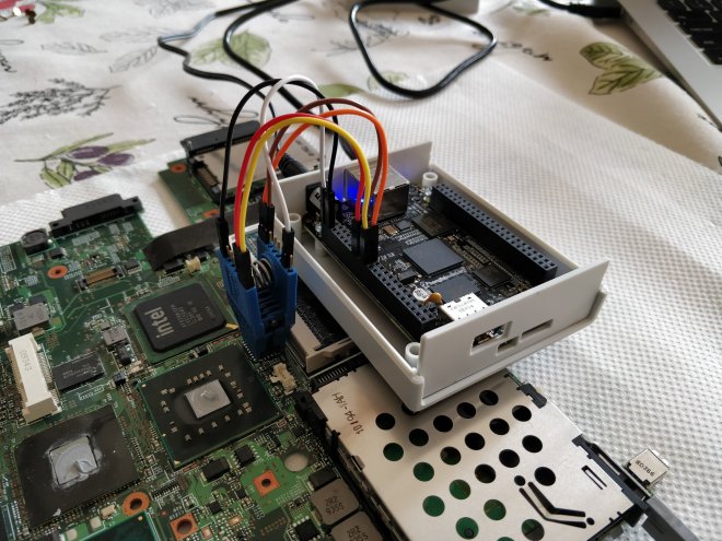
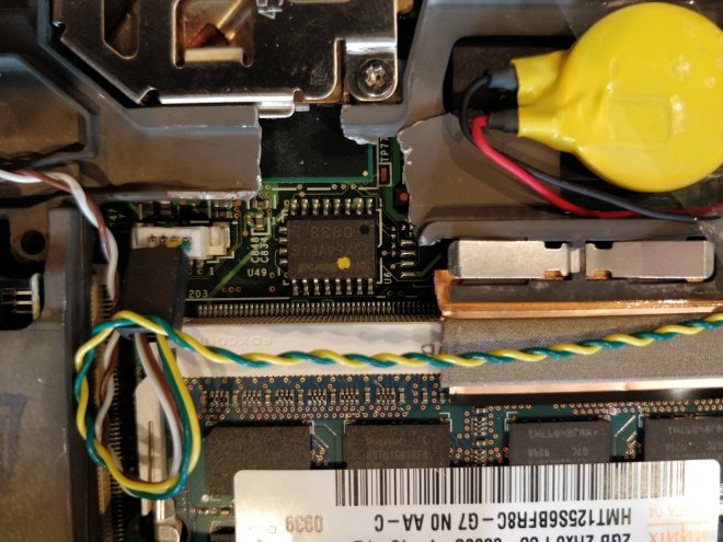
Unfortunately, ME write access is disabled for the host CPU, which prevents us from overwriting it using an internal flash — we’re gonna have to get out the external programmer. If you recall from last time, accessing the SOIC of the T500 required a laborious process of extracting the motherboard from the case, so this time I cut a little hole in the frame to make flashing easier. As it turned out, having this easy access port was very handy.


After reading back the ROM image, I decided to use try using me_cleaner, a tool for partially deblobbing the ME firmware on newer laptops, and for mine removing it entirely. Following the instructions for an external flash, we use the -S flag to clean the firmware.
$ python me_cleaner.py -S -O coreboot-nome.rom coreboot-orig.rom
Full image detected
Found FPT header at 0x1010
Found 13 partition(s)
Found FTPR header: FTPR partition spans from 0xd2000 to 0x142000
ME/TXE firmware version 4.1.3.1038 (generation 1)
Public key match: Intel ME, firmware versions 4.x.x.x
The meDisable bit in ICHSTRP0 is NOT SET, setting it now…
The meDisable bit in MCHSTRP0 is NOT SET, setting it now…
Disabling the ME region…
Wiping the ME region…
Done! Good luck!
After wiping the image, we can use ifdtool again to see that the ME region has been completely erased.
00000000:00000fff fd
00600000:007fffff bios
005f6000:005f7fff gbe
005f8000:005fffff pd
While this is the most sure-fire way to ensure the ME has been disabled, it’s not perfect — on boot the ME coprocessor will still attempt to read from its firmware in the flash region, and finding it not there will hang in an error state. However, it has been discovered through reverse engineering that Intel has incorporated various bits into the IFD that will disable the ME soon after boot. (One of these, the High Assurance Platform “HAP” bit, was incorporated at the request of the US government, which also understands the security risks of an unfettered ME.) For my laptop, this consists of setting two bits in the ICHSTRP and MCHSTRP, which me_cleaner does by default. After enabling this, the ME should gracefully shutdown after boot, which hopefully will cause the fewest system stability issues.
Finally after all that, let’s use ifdtool again to unlock all regions of the flash chip, which should ideally negate the need of ever doing an external flash again.
$ ifdtool -u coreboot-nome.rom
Let’s write it! Unlike last time we write the entire image, not just the BIOS region.
$ flashrom -p linux_spi:dev=/dev/spidev1.0,spispeed=4096 -w coreboot-nome-unlock.rom
Now the moment of truth. After hitting the power button … nothing. Gah.
Well, not exactly nothing. The screen doesn’t turn on, but the CD drive is making noises, so it’s not completely dead. Hmmm, let’s try again, but this time only setting the disable bits without wiping the ME region. This can be done using the -s flag of me_cleaner (which incidentally has a bug that required a small patch).
$ python me_cleaner.py -s -O coreboot-nome.rom coreboot-orig.rom
Reflashing again … same problem. Nothing.
Not completely sure what to do and worried that the ME was actually needed to boot, I decided to flash a pre-compiled Libreboot image on the laptop, which has the ME disabled out of the box and should hopefully Just Work. … And it did! The computer booted gracefully into the OS with no glitches or stability issues that I could see. Perfect. So disabling the ME is technically possible, but how exactly do I do it? Asking around a bit on IRC, I was directed to the coreboot bincfg utility, which is capable of generating an ME-less IFD from scratch. Following this similar guide for the X200, I was able to piece together a complete ROM.
First, we need to generate a new IFD. The bincfg directory contains configuration files for the X200, which we can fortunately re-use since the T500 has the same controller hub.
$ bincfg ifd-x200.spec ifd-x200.set ifd.bin
This IFD comes with only three regions, and has the ME disable bits set by default.
00000000:00000fff fd
00003000:007fffff bios
00001000:00002fff gbe
There are also configuration files for generating a new GbE region, but that requires certain fiddlings with the MAC address that I don’t know how to do — for now we can re-use the GbE from the old ROM, using ifdtool to chop it out.
$ ifdtool -x coreboot-orig.rom
File coreboot-orig.rom is 8388608 bytes
  Flash Region 0 (Flash Descriptor): 00000000 - 00000fff
  Flash Region 1 (BIOS): 00600000 - 007fffff
  Flash Region 2 (Intel ME): 00001000 - 005f5fff
  Flash Region 3 (GbE): 005f6000 - 005f7fff
  Flash Region 4 (Platform Data): 005f8000 - 005fffff
$ mv flashregion_3_gbe.bin gbe.bin
Next, we place the IFD and GbE regions in a blobs directory in the root of the coreboot tree, and then direct the build system to use them when generating an image. Here are the menuconfig settings:
General setup ---> [*] Use CMOS for configuration values
              ---> [*] Allow use of binary-only repository
Mainboard ---> Mainboard vendor ---> Lenovo
          ---> Mainboard model ---> ThinkPad T500
          ---> Size of CBFS filesystem in ROM (0x7fd000)
Chipset ---> [*] Add Intel descriptor.bin file (blobs/ifd.bin)
        ---> [*] Add gigabit ethernet configuration (blobs/gbe.bin)
        ---> Protect flash regions ---> Unlock flash regions
Devices ---> Display ---> Linear "high-resolution" framebuffer
Payloads ---> Add a payload ---> SeaBIOS
         ---> SeaBIOS version ---> master
Note that since the ME and Platform Data regions have been deleted from the new layout, we can expand the CBFS to the entire bios size — 0x7fd000 bytes, nearly the entire flash chip. This will allow in the future installing bigger and more interesting payloads, such as GRUB or LinuxBoot.
Finally, I wrote this new image to the flash chip. It worked. Huzzah!
After installation, we can check the status of the ME using intelmetool.
$ sudo intelmetool -m
Can't find ME PCI device
Perfect.
