Announcing coreboot 4.1

Dear coreboot community,

It has been more than 5 years since we have “released” coreboot ‘4.0’.
That last release marked some very important milestones that we originally prototyped in the abandoned LinuxBIOS v3 efforts, like the coreboot filesystem (CBFS), Kconfig support, and (strictly) separate device trees, build logic and configuration.

Since then there have been as many significant original developments, such as support for many new architectures (ARM, ARM64, MIPS, RISC-V), and related architectural changes like access to non-memory mapped SPI flash, or better insight about the internals of coreboot at runtime through the cbmem console, timestamp collection, or code coverage support.

It became clear that a new release is overdue. With our new release process only slowly getting in shape, I decided to take a random commit and call it ‘4.1’.

The release itself happens at an arbitrary point in time, but will serve as a starting point for other activities that require some kind of ‘starting point’ to build on, described below.

Future releases will happen more frequently, and with more guarantees about the state of the release, like having a cool down phase where boards can be tested and so on. I plan to create a release every three months, so the changes between any two release don’t become too
overwhelming.

With the release of coreboot 4.1, you get an announcement (this email), a git tag (4.1), and tar archives at http://www.coreboot.org/releases/, for the coreboot sources and the redistributable blobs.

Starting with coreboot 4.1, we will maintain a high level changelog and ‘flag days’ document. The latter will provide a concise list of changes which went into coreboot that require chipset or mainboard code to change to keep it working with the latest upstream coreboot.

For the time being, I will run these efforts, but I’ll happily share documentation duties with somebody else – it is a great opportunity to keep track of things, learn about the project and its design and various internals, while contributing to the project without the need to code.

Please contact me (for example by email or on IRC) if you’re interested, and we’ll work out how to collaborate on this.

The process should enable users of coreboot to follow releases if they want a more static base to build on, while making it easier to follow along with new developments by providing upgrade documentation.

Since moving away from a rolling (non-)release model is new for coreboot, things may still be a bit rough around the edges, but I’ll provide support for any issues that arise from the release process.

Patrick

[GSoC] EC/H8S firmware week #6

This week I looked at the communication between the EC H8S and the PMH4. The PMH4 (likely power management hub) is an ASIC which takes care of the power control. It controls who get’s power and who not. It doesn’t do any high level work, more like a big logic gatter. The PMH4 has inputs from several power good pins from different power rails and chips. On the output side it controls some power rails. It can also reset the H8S. The PMH4 also knows over some pins in which power state (ACPI S0,S4,S5) the board is. It doesn’t do any high level work. It’s more like a big logic gatter. There are no ADC on any power lines.

The PMH4 is connected to the H8S via 4 Pins. ~OE LE DATA CLK.

gsoc 2015 pmh4 connector t40

I connected a buspirate in SPI sniffer mode to debug the protocol. But the output looked a little bit strange. There was no data from the PMH4 to H8S (MISO) and the data comes in burst. To get more knowledge on the protocol I used a digital oscilloscope.

pmh4 oscilloscope

The protocol doesn’t look like SPI. LE get’s low after every transmission, ~OE is just high, clock and data just transfer the data. Sometimes when the H8S gets an interupt the Clock pause for some time and continues with the data afterwards. The clock is around ~400kHz.

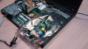
I confirmed the protocol via the oscilloscope, but still I don’t get any sign from the board. No fan, nothing else. There must be more than this single transmisison. Maybe the board is to much damaged. My modified board was already broken when I got it. There is a loose connection related to the cardbus. Maybe this is my problem I don’t know.

I’ve two board with two connectors for the PMH4 here. Why not using the OEM one as starter help for the other one?

t42 gives some starting help

I think the PMH4 does what it should do. The H8S has an digital-analog-converter pin connected to the video brightness. But I haven’t implemented it yet. But I don’t think the device booted, because neither the CPU nor the chipset produce any heat. Ok, maybe it does, I only used my finger as thermometer. A thermal camera would help here. I’ll borrow a thermal camera for that.

There are lot of pins which I ignore atm. E.g. A20 pin. Is there something to do in a specific time serie?

What’s next?

  • build a small protocol sniffer for the PMH4 XP using a msp430 or stellaris arm
  • make progress on the bootloader
  • find a way to flash back the OEM H8S firmware
  • find a way to flash my bootloader via OEM flash tools

My requirements to the bootloader are

  • UART flashing via XMODEM
  • a simple UART shell
  • I2C as recovery and shell as well

I2C pins are a lot easier to find and modify than the H8S UART. I’m not yet sure if the H8S should be the master or the slave and on what address he should use? Multiple? UART tx is working. Rx is a task to do.

PMH4 / PMH7 / Thinker communication

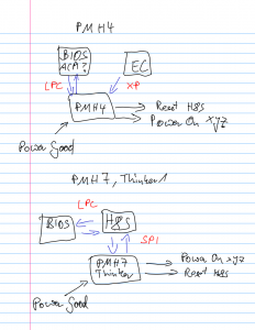
On newer board the PMH interfaces changed (>= x60, t60, …). They merge the LPC interface and the XP interface into an protocol over SPI. And the new PMH is used as GPIO expander as well.

pmh4 pmh7 thinker communication


[GSoC] EC/H8S firmware week #5

The T40 is flashing leds! The toolchain is still a little bit tricky. I’m using the debian package gcc-h8300-hms, written a small linker script and took the startup assembly routine from Johann Gysin’s led radiator.

Now I can flash leds. But what about booting the board? I would say it’s enough to put

  • (!MAINOFF) = high
  • FAN ON = high
  • pulse high on (!PWRSW_H8)

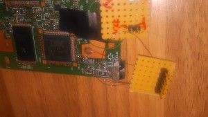
But it’s not enough. Also the FAN isn’t starting to rotate. I’ll try to debug every pin this week and solder some debug pins for the 2nd EC (PMHx) to the my modified T40 as well as to an unmodified T42p. The H8S is talking to the PMHx via SPI, while the H8S is the master and is doing bit banging SPI in software, because it doesn’t have a hardware unit for that. I’ll also use these pins for testing my SPI implementation. I’ll try to reuse an open source SPI implementation.

I also asked me if it’s a good idea to port coreboot for the T40 before continuing any efforts to the EC, but it’s a little bit harder, because the T40 uses a LPC/FWH flash in a TSOP40 case. Another option is changing the hardware to a board which is already supported by coreboot like a x60/t60 or x201. But it’s much more harder to access the 8 pins for flashing the EC on these boards.

Before switching to another board, the powersequencing must work and I need a robust recovery way, because when you kill the EC by flashing a new firmware, you don’t get a second chance, unless you solder a lot. Chrome EC fix this problem by splitting the EC firmware into 2 parts. One read-only part and one read-write’able part. Only the second part gets updated and the read-only part can at least boots the device.

Before starting the H8S port for Chrome EC I want to have a bootloader. Because it would improve developing speed. I think implement this is much faster than doing the full Chrome EC support and most of the bootloader code can be re-used for Chrome EC.

I’m also not perfectly sure Chrome EC is the best solution. It’s special use-case is EC, which is perfect. But neither the documentation (I think there is more than one page) nor the bugtracker is public. Thus it makes difficult to use. I’m also not sure if Chrome EC would apply my H8S port into their repository.

[GSoC] End user flash tool – week #4 #5

Hello! During week #4 and #5 I worked on several cases:

  1. Integration of cbfs_tool features.
  2. Improving libflashrom querying functions / integrating already existing patches.
  3. Extending and improving GUI.
Integration of cbfs_tool features

cbfs_tool is bigger project than bios_extract, so I took a little more to integrate it than during bios_extract integration as I needed to do some investigation how it works. I imported code related to:

  • creating rom file
  • adding components like stage, payload, option rom, bootsplash etc.
  • printing rom content
  • deleting components.

The same like in case of libflashrom and bios_extract I created a static library and linked it with flash tool.

IMPROVING LIBFLASHROM querying functions / integrating patches

After posting my draft patch for initial review on flashrom mailing list I got great feedback which helped me a lot. Urja Rannikko and Stefan Tauner pointed my mistakes and proposed improvements, moreover Anton Kochkov shared his libflashrom changes where he worked on similiar issues.  This community is really helpful. Thanks!

So, I did improvements in querying functions. Currently we have:

const char** fl_supported_programmers(void);
const char* fl_version(void);
fl_flashchip_info *fl_supported_flash_chips(void);
fl_board_info *fl_supported_boards(void);
fl_chipset_info *fl_supported_chipsets(void);
int fl_supported_info_free(void *p);

Unnecessary functions which return number of supported hardware of certain type have been removed. Now we can call functions to allocate the table and get a pointer to it. Of course I will create a patch and post it for second review.

I had a problem as my SOIC clip did not arrive on time, I was not able to test operations related functions on my T60. Actually it was my fault because I have not noticed a comment on internet auction that it may go from China. I have been waiting for 3 weeks for its arrival. Now I already have it so my main focus this week is to test libflashrom on real hardware.

extending / improving gui

I extended a GUI part to allow user to manipulate with rom contents like adding payload, bootsplash etc. and also removing such components. Of course this is not a main purpose of my project. The main focus is to create a tool which will allow user to don’t care about which options are correct. I will be going in this direction, I want to automate a process of creating a coreboot image as much as possible. So currently this is a kind of ‘advanced mode’. I implemented it for several reasons:

  • after integration of bios_extract, cbfs_tool and libflashrom it was not big effort to do it
  • implementing and testing it helped me to better understand integrated code and its features
  • there are also advanced users who may want to do some manual changes

Tasks for current week:

  • test probing, reading, flashing with libflashrom on T60 (through linux_spi)
  • GUI improvements proposed by Stefan Tauner(searching, sorting and filtering in supported hardware screen)
  • code cleanup

[GSoC] EC/H8S firmware week #3|4

In the last 2 weeks I managed to flash the H8S on the T40 using the OEM Renesas Flash Tool including their flash application. Flashing works in 2 steps, first upload a flash application into the H8S. Second this flash application will receive the firmware (via serial) and write it into the flash. Thanks to Renesas this application is available in source code. I would like to write an own flasher later.

But I wasn’t able to create a proper application yet. I could write the led programm in assembly, but having a working c compile is needed anyway.

I built a toolchain with gcc 4.9.2. The toolchain buildscript is very simple and can be found on github. I stopped my building efforts for now (building one based on gcc 4.4.6). There’s also a debian package for h8300 (based on gcc 3.4.6) which may be a good alternative. Before continuing in building toolchains and my led application, I’m reading me into linkerscipts and take a look how the compiler is working (e.g. what must a crt0 do?).

At the moment I know how the application should be compiled, where the reset vectors are and where the entrypoint. But putting these things together into a binary image is my task now.

The dev board I mentioned in my last post was stuck by the german post for the last 2 weeks, because there were on strike. The board is now in the custom office and I’ll collect in the next days, which will takes severals hours in Berlin.

[GSoC] coreboot for ARM64 Qemu – Week #3

For the week 3, I started to build the coreboot image to run on the target arm64 qemu. As soon as I started, I had to face a big red flag, a toolchain building error! The new toolchain (v1.31) failed to build on MacOSX. Despite several attempts, binutils failed to build and I couldn’t get the toolchain running. /buildgcc also failed on OSX due to missing string search for clang. Marc kindly help me out on this by introducing a small patch on this front. I also tried using the actual gcc and g++ (and not the innate gcc and g++ on OSX which are just symlinks to clang) but couldn’t rectify the toolchain build error.  But strangely, when I tried to build an older toolchain (v1.24) on the same machine, it worked. Confused, I decided to move forward with the build with the old toolchain itself.

I had to make some modifications on the src/mainboard/emulation/Kconfig, to bring up the new emulation mainboard. After this, I was able to successfully generate a configuration by running make menuconfig.

Next step was to make and generate the build/coreboot.rom. I have been facing some errors while building which I have been resolving on the way. The plan for this week is to finish the build. I also want to look at solving the toolchain building issue. Stepan said that the new toolchain hasn’t been tested on OSX, so this should provide some useful insights.

[GSoC] End user flash tool – week #3

During week 3 I worked on integrating bios_extract tool. I did analysis of code, understood it a bit and thought: “Nice, it should be fast and easy, I just need to do few changes”. Was it? Not completely.

After my analysis I knew that I need to do three things:

  • change main function to a function which I could invoke from GUI
  • redirect logs to GUI
  • make it possible to select output directory for extracted individual modules

I implemented it and decided that best solution will be to pack object files to static library. I compiled it and linked with my app, then I tried to extract a BIOS image and – BAM! – segmentation fault. Hmm, I did not change anything in extraction logic, so where I messed up? I started reverting my changes – segfault, segfault, segfault. I reverted almost all changes – still segfault. I downloaded bios_extract again and tried to first create object files from unchanged code, then build standard bios_extract app and apply my changes one by one. I compiled without any changes, tried to run bios_extract and… segmentation fault. I tried to compile with provided Makefile – it worked. Whoops, I missed checking Makefile content. This caught my attention:

CFLAGS ?= -g -fpack-struct -Wall -O0

fpack-struct? What is this sorcery? I googled it. Aha! Got you! This compiler flag packs all structure members together without holes, so structure alignment is not applied. Now it was obvious why I had segmentation faults, even if code was the same it worked differently because of different spaces between structure members. From this moment it was fast and easy 🙂

So, bios_extract is already integrated, it is possible to select rom file, select output directory and extract submodules there. Of course bios_extract log output is redirected to GUI. This is good, I can use rest of the week to work on libflashrom, my SOIC clip did not arrive yet, so I am still not able to test operation related functions, but already have feedback about my modifications applied to previously existing libflashrom patch, so I can start improving it – big thanks for review!

[GSoC] coreboot for ARM64 Qemu – Week #2

I spent the previous week working on the architecture of the qemu port. I made an attempt to dive into the internals of memory mapping for armv8. And then formulated an initial memory map structure for the armv8 port. After that I moved into developing some code. The most challenging aspect of this was moving to and fro between the qemu-armv7 existing port and the foundation-armv8 patches (now depreciated) of chromium and extracting the required modifications. My current work is building on qemu-armv7  taking inspiration on some aspects from the foundation armv8 which cater to the alterations required for 64-bit.

I then moved onto developing the default mem_uart which would be used in our emulation. After writing up a backbone for this new port, Marc suggested I push to gerrit and seek some reviews on it there. This was an important change from the development strategy I followed last year, when I did all the development locally and then pushed the end results to gerrit. This year, I would be following a more dynamic approach, with a continuos review-and-modify development cycle.

My plan for this week involves starting to build the firmware written thus far. I will look to load the built firmware in qemu and try getting some output on the console and finally get qemu-debug up and running.


[GSoC] End user flash tool – week #2

This week I started with adding new functions to libflashrom. I added 3 functions which purpose is to return a list of supported hardware:

int fl_supported_flash_chips(fl_flashchip_info_t *fchips);
int fl_supported_boards(fl_board_info_t *boards);
int fl_supported_chipsets(fl_chipset_info_t *chipsets);

For example, to obtain a list of supported boards, you can create an array of structures fl_board_info of suitable size, then pass it to fl_supported_boards(fl_board_info_t *boards) and you will have it filled with data, but how do you know what size your array should have?

There are other 3 functions which return number of supported hardware of certain type:

int fl_supported_flash_chips_number();
int fl_supported_boards_number();
int fl_supported_chipsets_number();

Work on libflashrom is still in progress, but as you can see some changes are already made, so I thought that it will be good idea to send a patch just for initial review to know if I am going in a good direction, so I sent a patch to flashrom mailing list.

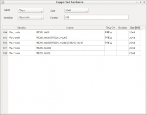
With use of these functions I was able to extend GUI part of coreboot end user flash tool and add screen which shows list of supported chips, boards and chipsets – screen.

I also started writing unit tests for GUI part, I wanted to use googletest framework, but finally decided to go with QtTestLib as it provides easy introspection for Qt’s signals and slots.

After all of this work I am more familiar with flashrom codebase, but still have much to do and learn, now comes hard, but exciting part – testing and fixing functions related to operations – like reading, verifying, erasing and flashing. Some of flashrom functions previously used in libflashrom are now static or do not exist anymore. I ordered  ThinkPad T60 laptop and SOIC clip for testing purposes, T60 already arrived so lets start disassembling it!

[GSoC] EC/H8S firmware week #2

The last week was a little bit depressive. I did the some resoldering. Pin P90 wasn’t connected to 3.3V which is needed to enter the flash boot mode. It was soldered  to the VCC of the Serial level shifter MAX3243. After searching some minutes with the Multimeter for a better power source, I decieded to use 3.3V near the H8S. It’s now a very long cable across the board.

Now let’s see, how good this works? Nothing :(. Recheck with a voltmeter and found another problem with P91 (/SUS_STAT). When connecting SUS_STAT with an 1k resistor to 3.3V the voltmeter shows 0.04V. This means it’s driven by something else to 0V. My hope was that the chipset isn’t driving this until it’s powered. But sadly it is driving it to 0V. What’s SUS_STAT? SUS_STAT can be used as LPCPD (LPC power down) and is used to notify devices to enter a low power state soon. Suspend Status is active low, which means all device should be in low power mode.
What should I do now? I need 3.3V on that line.

There are multiple solution:

  • Remove 1k and burn it to death. But likely this could kill the chipset or
    a least this certain pin or multiple pins
  • Cut the pin
  • Bend the pin upwards while desoldering
  • Desolder the whole chip and bend afterwards, resolder
  • Replace the chip with a socket (expensive and rare)

This decision is not easy to take, especially because I never done most
of these things. This got me stuck for a while until Peter helped me out,
he bend a single pin upwards. Thanks!

The next week milestone is still flashing the EC, the same goal since the first week. So the time schedule will be a little big chaotic. Maybe I can hurry up and reach another weekly goal fast than a week.

Because I was stuck on that a little bit, I took another look on ebay and bought a development board with a H8S/2633. 2633 is a little bit newer than the 2100 series
which is used in Lenovo laptops. The board should arrive in one week, but atm it’s in german customs. Such development boards are hard to get for a “good” price. Brand new boards start with several hundred euros or dollars. E.g. the debugger E10 (USB device) cost around 1000 Euro, it’s only a stupid USB device. I already bought on ebay an E8, previous generation debugger, but it can not debug the chip, only flash them with the Renesas software/IDE.

Beside my project I’ve done some other work on coreboot. I helped Holger Levsen on creating a reproducible build job for coreboot on reproducible.debian.net. More info about reproducible builds are on their wiki page.  To improve reproducibility I created 2 patches #10448 #10449. They cleaned up reproducible bugs in coreboot and without building Payloads, most targets are now reproducible. Great thanks to Holger Levsen for his work on that!