Converged Security (CBnT) coreboot support and tooling

Converged Security (CBnT) coreboot support and toolingWe are happy to announce that the Converged Security Suite got some major updates and arrived at release version 2.6.0. Not only does this release provide new features, but also comes with a new look! Thanks to the design team at 9elements.com we do have our own logo now.
Converged Security (CBnT) coreboot support and tooling
Some time ago we renamed the TXT-Suite to Converged Security Suite in order to cover more than just Intel Trusted Execution Technology. Now we are making the first step into this direction by releasing the new cbnt-prov tool as part of the 9elements CSS. We here at new 9elements are passionate about security and open-source firmware - and we had the chance to enable Intel Converged Boot Guard and TXT on coreboot-based platforms. Our development platform was the new OCP Deltalake from Facebook, which has been presented on the OCP Virtual Summit 2020.

Intel Converged Boot Guard and TXT

Intel introduced CBnT as an addition to the already present Intel Trusted Execution Technology and Intel Boot Guard. The plan was to merge both technologies together into one - namely CBnT. Intel does rely on so called Authenticated Code Modules (ACMs) which get executed by the CPU, and are signed by Intel - so that only Intel-signed ACMs can run a very specific set of CPUs. Prior to CBnT, there have been two seperate ACMs for either Bootguard or TXT - However with CBnT Intel merged both ACMs together such that there are now two types of ACMs; The Startup ACM and the SINIT ACM. The Startup ACM does establish the Static Root of Trust, where as the SINIT ACM does empower the Dynamic Root of Trust. In the previous version of Intel TXT, the Trust Anchor was the TPM. Intel CBnT moves that Trust Anchor into the Intel Management Engine. In addition, the policies have been defined in the non-volatile part of the TPM, the NVRAM. With Intel CBnT, Intel introduced changes such that you now have two structures to configure Intel CBnT. The first structure is the Key Manifest (KM). The KM closes the gap between Intel Management Engine and Firmware. On one hand, the KM contains a hash of the public key with which the second structure, the Boot Policy Manifest (BPM) has been signed - to validate that only BPMs signed with a certain private key are deemed to be valid. On the other hand, the KM itself is also signed - and the hash of the public key of the KM signing key is burned into the ME.
Converged Security (CBnT) coreboot support and tooling
Chain of Trust for Intel CBnT

CBnT-Prov Tooling

The newly introduced cbnt-prov tooling can be used to generate and sign the Key Manifest and the Boot Policy Manifest for Intel CBnT. It can also generate the keys needed for signing the manifests, and stitching them back into the firmware. The cbnt-prov tooling is firmware agnostic - it does not care if you use UEFI or open-source firmware like coreboot. It works with any firmware as long as the firmware respects the Intel CBnT and FIT specification. Extensive Documentation on how to build and use the cbnt-prov tooling can be found here. We do also landed a couple of patches to integrate this tooling directly into the coreboot toolchain, such that one can seamlessly build coreboot with CBnT support enabled - all needed structure can automatically be generated through buildchain - or optionally one can hand in just the binaries. This enables customer to take full control over the CBnT Provisioning process with open-source code - transparent and open.

coreboot Support

As mentioned earlier, we did land a couple of patches to integrate CBnT into coreboot - not only the CBnT Technology itself, but also the KM and BPM can be generated through the toolchain.
Converged Security (CBnT) coreboot support and tooling
CBnT Support in coreboot
In the coreboot > Security menu, one can not enable Intel CBnT Support. Once enabled, the user needs to point to the Startup- and S-ACM location, and needs to define if the KM, BPM should be either generated, optionally signed, or if the user hands in binaries.
Converged Security (CBnT) coreboot support and tooling
CBnT Tooling support in coreboot
Once the user defined KM and BPM options, the coreboot toolchain will build, sign and integrate the KM and BPM structures automatically into the coreboot firmware image - easy!

Why Open-Source Tooling Matters

The Converged Bootguard and TXT (CBnT) Technology is the backbone of your firmware security. It secures what is under your control - the first code that runs on the platform, the so called Initial Boot Block (IBB) and builds up the chain-of-trust for your hardware. Based on the measurements takes by your firmware and the CBnT technology, your security models decides if the machine is trusted or not. And the structures defining those parameters are placed in the KM and the BPM. A wrongly configured KM and BPM can either brick your machine so that your infrastructure does not boot up anymore - or even worse can introduce security flaws which open up an attack window. Thus the owner of the machine should have full control of what should be configured on the machine and even more important have the ability to check what has been configured - to verify the correctness of the applied configuration. These goals can only be achieved through open-source tooling - to give the owner of the hardware full transparency on what has been configured, and the ability to configure the machine to their needs.

Get Involved

The tooling can be found in our repo here: https://github.com/9elements/converged-security-suite/ We are currently working on a CBnT Testsuite and BootGuard Provisioning - so expect more updates here soon! Do you need help with your firmware project? Or want to talk about firmware security with us? Contact us!

A short journey to x86 long mode in coreboot on recent Intel platforms

While it was difficult to add initial x86_64 support in coreboot, as described in my last blog article how-to-not-add-x86_64-support-to-coreboot it was way easier on real hardware. During the OSFC we did a small hackathon at 9elements and got x86_64 working in coreboot on recent Intel platforms. If you want to test new code that deals with low level stuff like enabling x86_64 mode in assembly, it's always good to test it on qemu using KVM. It runs the code in ring 0 instead of emulating every single instruction and thus is very close to bare metal machines.

$ qemu-system-x86_64 -M q35 -accel kvm -bios build/coreboot.rom

But, running coreboot's x86_64 code on KVM gave more magic errors than you could find in books about some famous magician with a scarf on his forehead. To summarize:
  • On recent AMD platforms it stops after entering x86_64 long mode.
  • On older Intel platforms everything works.
  • On recent Intel platforms after entering long mode every instruction causes a fault, and thus the instruction is emulated by the kernel, which doesn't handle FPU instruction that well...
  • On recent Intel platforms the MMU aborts walking page tables and returns the data within the page table itself when looking up some virtual addresses...
Tests on real hardware, in this case the X11SSH-TF showed none of the problems above. After fixing integer-void pointer conversion (CB:48166) , (CB:48167) , (CB:48177) and adding assembly code to enable long mode in Cache-As-RAM (CB:48170) it booted straight to romstage. first boot console log:

coreboot-4.13-241-g52ab788549-dirty Tue Dec 1 18:23:08 UTC 2020 bootblock starting (log level: 7)... CPU: Intel(R) Xeon(R) CPU E3-1240 v6 @ 3.70GHz CPU: ID 906e9, Kabylake H B0, ucode: 000000d5 CPU: AES supported, TXT supported, VT supported MCH: device id 5918 (rev 05) is Kabylake DT 2 PCH: device id a149 (rev 31) is Skylake PCH-H C236 IGD: device id ffff (rev ff) is Unknown FMAP: Found "FLASH" version 1.1 at 0xb10000. FMAP: base = 0xff000000 size = 0x1000000 #areas = 4 FMAP: area COREBOOT found @ b10200 (5176832 bytes) CBFS: Found 'fallback/romstage' @0x80 size 0xe334 BS: bootblock times (exec / console): total (unknown) / 53 ms

coreboot-4.13-241-g52ab788549-dirty Tue Dec 1 18:23:08 UTC 2020 romstage starting (log level: 7)... pm1_sts: 0900 pm1_en: 4000 pm1_cnt: 00000000 gpe0_sts[0]: 00000000 gpe0_en[0]: 00000000 gpe0_sts[1]: 00000000 gpe0_en[1]: 00000000 gpe0_sts[2]: 00000000 gpe0_en[2]: 00000000 gpe0_sts[3]: 00000000 gpe0_en[3]: 00000000 TCO_STS: 0000 0000 GEN_PMCON: e0810200 000018c8 GBLRST_CAUSE: 00000002 00000000 prev_sleep_state 0 FMAP: area COREBOOT found @ b10200 (5176832 bytes) CBFS: Found 'fspm.bin' @0x5fdc0 size 0x63000 POST: 0x34 FMAP: area RW_MRC_CACHE found @ b00000 (65536 bytes) MRC: no data in 'RW_MRC_CACHE' No memory dimm at address A2 No memory dimm at address A4 POST: 0x36 POST: 0x92 ghost It hung at entering FSP-M, which as it's a binary blob, wasn't automatically recompiled to x86_64. A wrapper (CB:48175) , written in assembly, fixed the problem by falling back to x86_32 when calling into FSP. The wrapper will automatically switch back into x86_64 mode when the function returns. This is slow, but as we don't have proper blobs there's no other way around it. memory init console log:

coreboot-4.13-242-g04129be978-dirty Tue Dec 1 18:42:20 UTC 2020 romstage starting (log level: 7)... pm1_sts: 0900 pm1_en: 0000 pm1_cnt: 00000000 gpe0_sts[0]: 00000000 gpe0_en[0]: 00000000 gpe0_sts[1]: 00000000 gpe0_en[1]: 00000000 gpe0_sts[2]: 00000000 gpe0_en[2]: 00000000 gpe0_sts[3]: 00000000 gpe0_en[3]: 00000000 TCO_STS: 0000 0000 GEN_PMCON: e0810200 000018c8 GBLRST_CAUSE: 00000002 00000000 prev_sleep_state 0 FMAP: area COREBOOT found @ b10200 (5176832 bytes) CBFS: Found 'fspm.bin' @0x5fdc0 size 0x63000 POST: 0x34 FMAP: area RW_MRC_CACHE found @ b00000 (65536 bytes) MRC: no data in 'RW_MRC_CACHE' No memory dimm at address A2 No memory dimm at address A4 POST: 0x36 POST: 0x92 POST: 0x98 FspMemoryInit returned 0x80000002 POST: 0xe3 FspMemoryInit returned an error!

The FSP was now able to run, but it returned an error Invalid parameter, which was due to the fact that FSP's config structures contained void pointers, which on x86_64 have a different size and doesn't match what FSP expects. Fixing those headers is an ongoing tasks, but was hacked around. SMM stack trash console log:

IOAPIC: Initializing IOAPIC at 0xfec00000 IOAPIC: Bootstrap Processor Local APIC = 0x00 IOAPIC: ID = 0x02 PCI: 00:1f.0 init finished in 9 msecs POST: 0x75 POST: 0x75 PCI: 00:1f.2 init RTC Init Set power on after power failure. Disabling ACPI via APMC.

coreboot-4.13-241-g52ab788549-dirty Tue Dec 1 18:23:08 UTC 2020 smm starting (log level: 7)... SMI_STS: PM1 APM SMI#: ACPI disabled. canary 0xcdcdcdcd7f9ff800 != 0x7f9ff800 SMM Handler caused a stack overflow ghostFinally it booted into SMM, but crashed due to stack trashing. That turned out to be a false positive, as the stack canary is the size of a void pointer and is written in x86_32 assembly, but checked in x86_64 C code and thus failed. Writing 4 additional bytes in assembly code fixed the stack canary check and it finally booted.(CB:48215) patch:

/* Write canary to the bottom of the stack */ movl   stack_size, %eax subl   %eax, %ebx /* %ebx(stack_top) - size = %ebx(stack_bottom) */ movl   %ebx, (%ebx) + #if ENV_X86_64 +   movl   $0, 4(%ebx) + #endif

Summarizing it took about a day to add x86_64 support and half of the code needed to be written in assembly code. With those patches in place it should be easier to port additional platforms to x86_64, reducing the time to a few hours. I invite everyone to play with the changes, hack the code and improve it to make this open source project even more awesome.

[GSoC] Ghidra firmware utilities, wrap-up

Hi everyone. The official programming period for GSoC 2019 is now over, and it’s time for final evaluations. I will use this post to summarize what I’ve worked on this summer, as well as how to use the Ghidra plugin.

The project is available on GitHub: https://github.com/al3xtjames/ghidra-firmware-utils

Project details

In my initial project proposal, I planned on writing various filesystem loaders (for hybrid PCI option ROMs, Intel flash descriptor images, coreboot File System images, and UEFI firmware volumes), a binary loader for legacy x86 PCI option ROMs, and a UEFI helper script. I ended up implementing all of these in the Ghidra plugin, and also worked on a UEFI Terse Executable binary loader. You can look at my previous blogposts to see my progress throughout the summer.

Here is a description of the components included in the project:

FS loaders allow files stored within binary images to be imported directly into Ghidra. The following FS loaders are implemented in this project:

Hybrid PCI option ROM

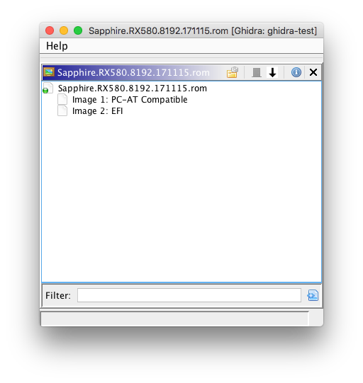
Some PCI option ROMs may contain multiple executable ROMs. This is usually used to support multiple firmware types (e.g. a video card with legacy BIOS VGA support and UEFI Graphics Output Protocol support). The FS loader allows each embedded executable ROM image to be imported.

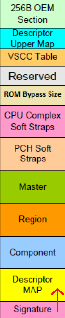
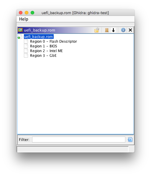
Intel firmware descriptor (IFD)

Recent Intel platforms have multiple regions on the SPI flash (used to store system firmware). The descriptor region describes the layout of these flash regions. The FS loader allows each flash region to be imported. Ghidra supports nested FS loaders, so other FS loaders (FMAP/CBFS or UEFI FV) can be used to parse certain regions, such as the BIOS region.

Flash Map (FMAP)

This is another standard for describing flash regions, used by coreboot and various Google devices. Like the IFD FS loader, this allows each defined flash region to be imported, and it can be used with other FS loaders (e.g. the COREBOOT region can be parsed with the CBFS loader).

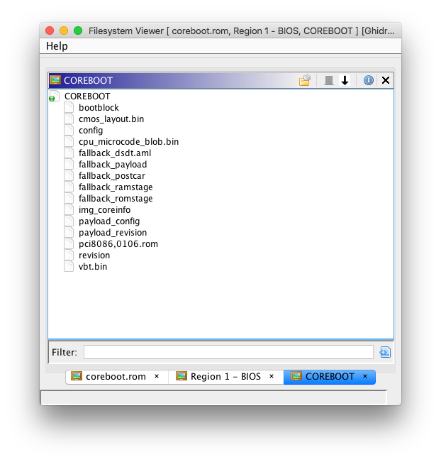
coreboot File System (CBFS)

coreboot uses a simple file system to store independent binaries and data files. The CBFS loader can be used to import each CBFS file for analysis; for example, PCI option ROMs stored as CBFS files can be imported. Optional CBFS file compression (LZ4/LZMA) is supported.

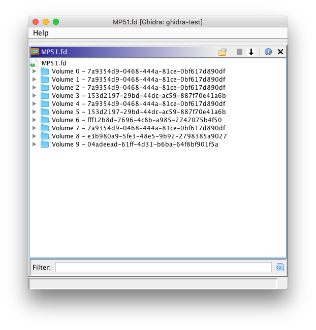
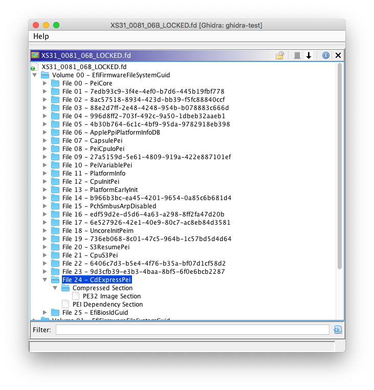
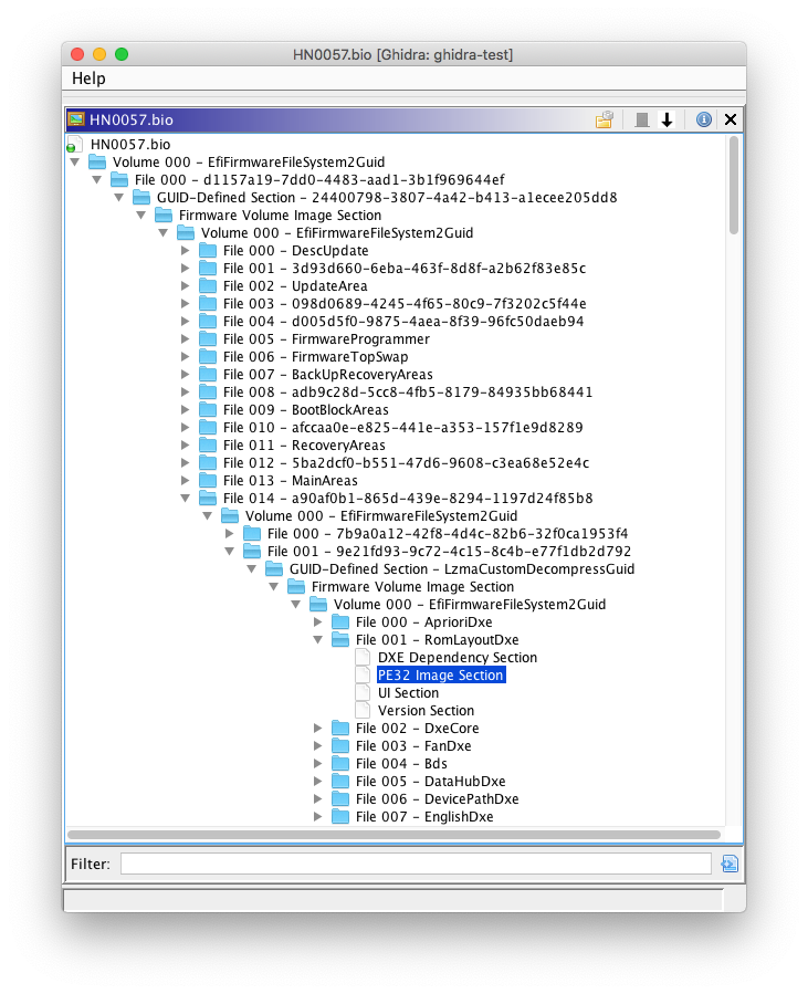
UEFI firmware volume (FV)/firmware file system (FFS)

UEFI firmware images use firmware volumes for storing firmware files, which may consist of multiple sections. The UEFI FV FS loader allows UEFI firmware volumes to be imported, including embedded firmware files/sections.

This project also implements a couple of binary loaders:

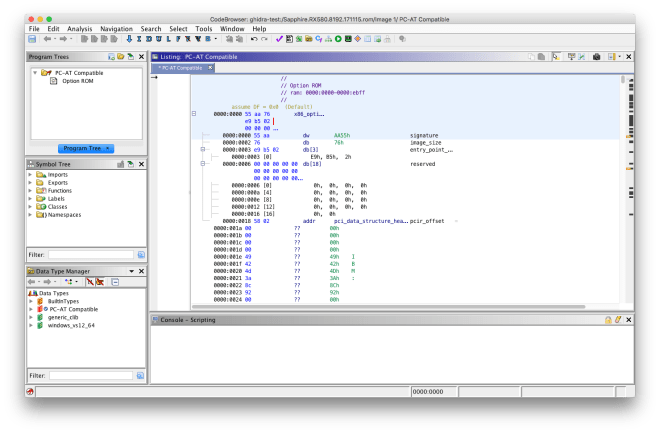
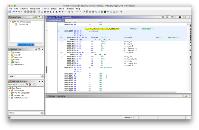
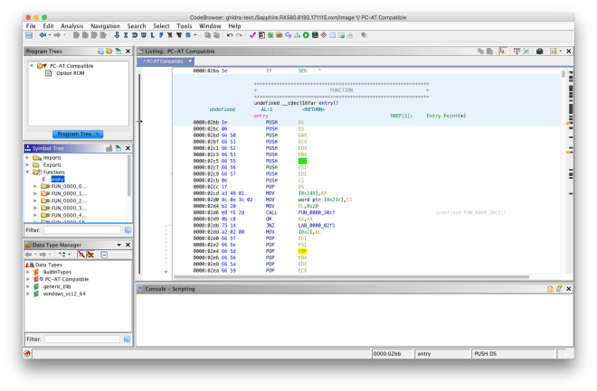
Legacy x86 option ROM

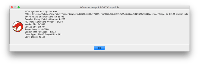
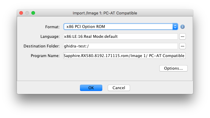
PCI option ROMs that target the x86 legacy BIOS contain a raw 16-bit executable image. They also have additional header fields, including a field with the entry point instruction. The binary loader resolves the entry point and specifies that 16-bit x86 disassembly should be used.

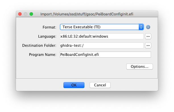
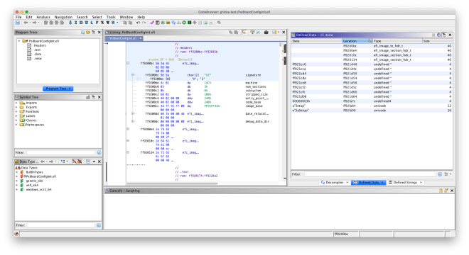
UEFI Terse Executable (TE)

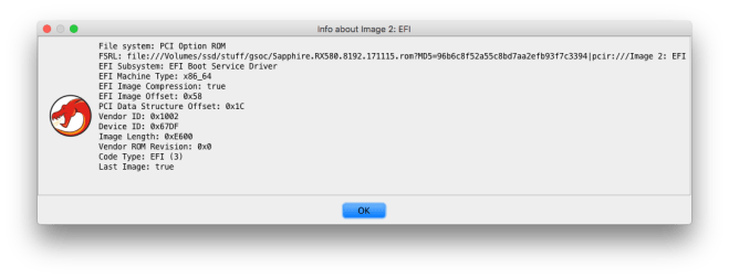
UEFI binaries can use one of two executable formats: the Portable Executable (PE32) format (also used on Windows), and the Terse Executable (TE) format. Terse Executables are essentially simplified PE32 binaries – the numerous DOS/NT/optional headers are condensed into a single TE header, without any superfluous header fields. The binary loader resolves the entry point and defines memory blocks corresponding to the sections defined in the TE header.

Finally, a helper script for assisting with the analysis of UEFI binaries is
included. The UEFI helper script does the following:

  • Imports a UEFI data type library
  • Defines the entry point signature
  • Searches for known EFI GUIDs in the .data/.text segments
  • Attempts to locate global EFI table pointers (gST/gBS/gRT)
  • Attempts to perform propagation of some EFI types to called functions

Project usage

Instructions for how to build and use the Ghidra plugin are included in the project’s README, but I’ll restate them here.

Building the plugin

Like other Ghidra plugins (and Ghidra itself), this project uses Gradle as the build system. Set the GHIDRA_INSTALL_DIR environment variable (point it to your Ghidra installation directory) and run gradle to build the plugin. Install the generated ZIP (in the dist directory) by selecting
File > Install Extensions in Ghidra, and then clicking the green plus icon.

Using the FS loaders

Load the specified input file into Ghidra (drag and drop or use File > Import File). Assuming the input file is supported by a FS loader, Ghidra should indicate that a container file was detected, and will allow you to batch import all enclosed files or view the file system.

Note that Ghidra does support parsing nested filesystems with multiple FS loaders. For example, UEFI firmware volumes in the BIOS region of an Intel firmware image can be parsed by first importing the Intel firmware image and then importing the BIOS region (select Import or Open File System in the right-click menu).

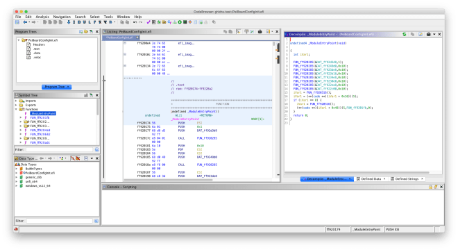
Using the UEFI helper script

After loading a UEFI executable (PE32 or TE), you can run the UEFI Helper script from the Script Manager window (under Window). Select UEFIHelper.java and click the green “Run Script” button.

Currently, the UEFI helper script assumes the entry point matches the standard driver/application signature (with EFI_HANDLE and EFI_SYSTEM_TABLE * parameters). SEC/PEI/SMM modules have different entry point parameters, which will have to be manually specified.

Future work

While my work for GSoC 2019 is complete, I think the following additions would be useful for this project (and UEFI reverse-engineering in general):

Processor module for disassembling EFI Byte Code (EBC)

EFI Byte Code is a byte code format used for platform-independent UEFI applications/drivers. Ghidra currently doesn’t support the EBC virtual machine architecture. Fortunately, it is possible to add support for an architecture by creating a SLEIGH processor specification.

Upstreamed Terse Executable loader

As previously described, TE binaries are very similar to PE binaries. Ghidra already has parsers for the data directory and section header structures, which are present in both PE and TE binaries. My TE loader had to reimplement these parsers, as the existing parsers depended on the NT header, which isn’t present in TE binaries. Removing the NT header dependency from the data directory/section header parsers would allow Ghidra’s existing parsers to be reused by the TE loader. This would also make it easier to upstream the TE loader.

Support for SEC/PEI/SMM modules (UEFI helper script)

Instead of assuming the entry point parameters, the script could prompt the user to select the module type, or somehow retrieve the module type from the FFS header (if the FS loader was used).

Additional GUID heuristics (UEFI helper script)

The script could locate calls to EFI_BOOT_SERVICES/EFI_RUNTIME_SERVICES functions with GUID parameters and automatically apply the EFI_GUID data type.

Protocol database (UEFI helper script)

Similar to the existing GUID->name database (imported from UEFITool), a database for mapping protocol definitions to the structure name could be created. The script could use this database to automatically apply the correct protocol structure type in calls to LocateProtocol/etc.

Very basic dependency graph (inspired by this UEFITool issue) (UEFI helper script)

The script could locate all calls to protocol consumption/production functions in EFI_BOOT_SERVICES (such as LocateProtocol, InstallProtocol, etc) and use this to generate a basic overview of the protocols used by the current UEFI binary.

Acknowledgements

I would like to thank my mentors Martin Roth and Raul Rangel for their continued assistance during the past 12 weeks. This has been a great opportunity, and it certainly wouldn’t have been possible without their help. I look forward to contributing to coreboot and other related projects (including Ghidra) in the future.
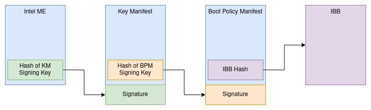
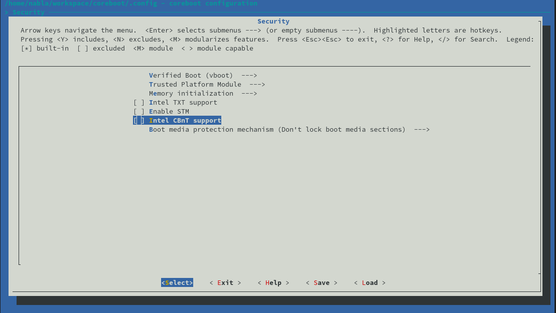
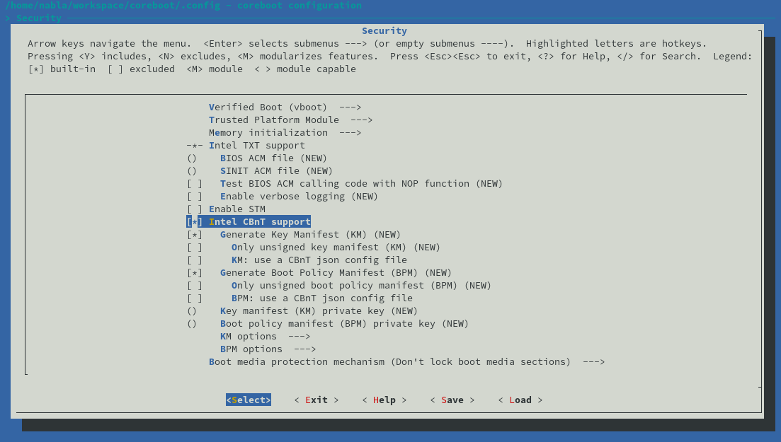
[GSoC] Ghidra firmware utilities, week 9

Last week, I finished up my work on the UEFI firmware volume FS loader. This was the last FS loader I planned on writing for this project, so now it’s time to work on writing additional binary loaders and helper scripts to assist with UEFI reverse engineering. During the past couple of days, I’ve been working on a loader for Terse Executable (TE) binaries.

For the most part, UEFI binaries are standard PE32(+) executables. Standard headers such as the DOS stub, COFF header, and image headers are present. In order to reduce the size of binaries required for UEFI Platform Initialization, the TE binary format was created. The TE header only includes the fields needed for execution, dropping unnecessary fields such as the DOS stub. TE binaries are otherwise similar to PE32 binaries. EDK2 has additional documentation regarding the TE header.

Like the existing PE32 binary loader, the TE binary loader defines the program sections and defines the entry point function. It can be used in conjunction with the UEFI firmware volume FS loader to import TE image sections for analysis.

The TE binary loader is included in the latest commit in ghidra-firmware-utils. As always, feel free to submit an issue report if you encounter any problems with it.

Plans for this week

I have started working on the UEFI helper script. This script aims to assist with UEFI reverse engineering by loading UEFI type definitions, defining GUIDs, and fixing the entry point.

[GSoC] Ghidra firmware utilities, weeks 6-8

Hello everyone. It’s been a few weeks since I’ve written my last blog post, and during that time I’ve been working on the FS loader for UEFI firmware images. This FS loader aims to implement functionality similar to UEFITool in Ghidra.

As described in the previous blog post, Intel platforms divide the flash chip into several regions, including the BIOS region. On UEFI systems, the BIOS region is used to store UEFI firmware components, which are organized in a hierarchy. This hierarchy begins with UEFI firmware volumes, which consist of FFS (firmware file system) files. In turn, these FFS files can contain multiple sections. Firmware volumes can also be nested within FFS files. This helpful reference by Trammell Hudson as well as this presentation from OpenSecurityTraining have some additional information regarding UEFI firmware volumes.

For example, a UEFI firmware implementation could have a firmware volume specifically for the Driver eXecution Environment (DXE phase). Stored as FFS files, DXE drivers within the firmware volume could consist of a PE32 section to store the actual driver binary, as well as a UI section to store the name of the driver.

So far, I’ve implemented basic firmware volume parsing in the FS loader; I’ve pushed this to the GitHub repository. Currently, this doesn’t handle FFS file or section parsing.

FFS file and section parsing is still a work-in-progress, but here’s a preview:

This is mostly complete, but there are still some nasty bugs related to FFS alignment that I’m working on fixing. My focus for this week is to finish up this FS loader.

Update (2019-07-19)

I have committed support for UEFI FFS file/section parsing in the GitHub repo. Please open an issue report if you encounter any issues with it (such as missing files/sections that UEFITool or other tools parse without issues).

[GSoC] Ghidra firmware utilities, week 5

Hi everyone. As stated in my previous blogpost, I have been working on a FS loader for Intel Flash Descriptor (IFD) images. The IFD is used on Intel x86 platforms to define various regions in the SPI flash. These may include the Intel ME firmware region, BIOS region, Gigabit ethernet firmware region, etc. The IFD also defines read/write permissions for each flash region, and it may also contain various configurable chipset parameters (PCH straps). Additional information about the firmware descriptor can be found in this helpful post by plutomaniac on the Win-Raid forum, as well as these slides from Open Security Training.

For a filesystem loader, the flash regions are exposed as files. FLMAP0 in the descriptor map and the component/region sections are parsed to determine the base and limit addresses for each region; both IFD v1/v2 (since Skylake) are supported. Ghidra supports nested filesystem loaders, so the FMAP and CBFS loaders that I’ve previously written can be used for parsing the BIOS region.

If you encounter any issues with the IFD FS loader, please feel free to submit an issue report in the GitHub repository.

Plans for this week

I have started working on a filesystem loader for UEFI firmware volumes. In conjunction with the IFD loader, this will allow UEFI firmware images to be imported for analysis in Ghidra (behaving somewhat similar to the excellent UEFITool).

[GSoC] Ghidra firmware utilities, week 3

Last week, I finalized my work on the PCI option ROM loader, which was the first part described in my initial proposal for this project. This consists of a filesystem loader for hybrid/UEFI option ROMs and a binary loader for x86 option ROMs.

Background information on PCI option ROMs

Option ROMs may contain more than one executable image; for example, a graphics card may have a legacy x86 option ROM for VGA BIOS support as well as a UEFI option ROM to support the UEFI Graphics Output Protocol. x86 option ROMs are raw 16-bit binaries. The entry point is stored as a short JMP instruction in the option ROM header; the BIOS will execute this instruction to jump to the entry point. In contrast, UEFI images contain an UEFI driver, which is a PE32+ binary. This binary can be (and frequently is) compressed with the EFI compression algorithm, which is a combination of Huffman encoding and the LZ77 algorithm.

Filesystem loader

The filesystem loader allows hybrid/UEFI option ROMs to be imported. It also transparently handles the extraction of compressed UEFI executables.

Initially, I attempted to write a Java implementation of the EFI Compression Algorithm for use in the FS loader, but ran into several issues when handling the decompression of certain blocks. I eventually decided to reuse the existing C decompression implementation in EDK2, and wrote a Java Native Interface (JNI) wrapper to call the functions in the C library.

With the FS loader, UEFI drivers in option ROMs can be imported for analysis with Ghidra’s native PE32+ loader.

x86 option ROM binary loader

This loader allows x86 option ROMs to be imported for analysis. Various PCI structures are automatically defined, and the entry function is resolved by decoding the JMP instruction in the option ROM header.

PCI option ROM header data type
PCI data structure data type
Disassembled entry point

Plans for this week

I’ve started to work on filesystem loader for FMAP/CBFS (used by coreboot firmware images). After that, I plan on working on additional FS loaders for Intel flash images (IFD parsing) and UEFI firmware volumes.

As usual, the source code is available in my GitHub repository. Installation and usage instructions are included in the README; feel free to open an issue report if anything goes awry.

[GSoC] Ghidra firmware utilities, weeks 1-2

Hi everyone. I’m Alex James (theracermaster on IRC) and I’m working on developing modules for Ghidra to assist with firmware reverse engineering as a part of GSoC 2019. Martin Roth and Raul Rangel are my mentors for this project; I would like to thank them for their support thus far.

Ghidra is an open-source software reverse engineering suite developed by the NSA, offering similar functionality to existing tools such as IDA Pro. My GSoC project aims to augment its functionality for firmware RE. This project will consist of three parts: a loader for PCI option ROMs, a loader for firmware images, and various scripts to assist with UEFI binary reverse engineering (importing common types, GUIDs, etc).

The source code for this project is available here.

Week 1

During my first week, I started implementing the filesystem loader for PCI option ROMs. This allows option ROMs (and their enclosed images) to be loaded into Ghidra for analysis. So far, option ROMs containing uncompressed UEFI binaries can be successfully loaded as PE32+ executables in Ghidra. The loader also calculates the entry point address for legacy x86 option ROMs.

Plans for this week

So far this week, I’ve worked on writing a simple JNI wrapper for the reference C implementation of the EFI decompressor from EDK2, and have used this to add support for compressed EFI images to the option ROM FS loader. Additionally, I plan on making further improvements to the option ROM loader for legacy option ROMs; while the entry point address is properly calculated, they still have to be manually imported as a raw binary.

Update: coreboot conference in Europe, October 2015

UPDATE: Invitations published, venue is decided, few bed+breakfast rooms at the venue are still available

TL;DR: coreboot conference Oct 9-11, more info at http://coreboot.org/Coreboot_conference_Bonn_2015


Dear coreboot developers, users and interested parties,

we are currently trying to organize a coreboot conference and developer meeting in October 2015 in Germany.

This is not intended to be a pure developer meeting, we also hope to reach out to manufacturers of processors, chipsets, mainboards and servers/laptops/tablets/desktops with an interest in coreboot and the possibilities it offers.

My plan (which is not final yet) is to have the Federal Office for Information Security (BSI) in Germany host the conference in Bonn, Germany. As a national cyber security authority, the goal of the BSI is to promote IT security in Germany. For this reason, the BSI has funded coreboot development in the past for security reasons.

The preliminary plans are to coordinate the exact date of the conference to be before or after Embedded Linux Conference Europe, scheduled for October 5-7 in Dublin, Ireland. Planned duration is 3 days. This means we can either use the time window from Thursday Oct 1 to Sunday Oct 4, or from Thursday Oct 8 to Monday Oct 12. The former has the advantage of having cheaper hotel rooms available in Bonn, while the latter has the advantage of avoiding Oct 3, a national holiday in Germany (all shops closed). UPDATE: Preliminary dates are Friday Oct 9 to Sunday Oct 11. The doodle has been updated accordingly. Thursday and Monday could be filled with some cultural attractions if desired.

ATTENTION vendors/manufacturers: If your main interest is forging business relationships and/or strategic coordination and you want to skip the technical workshops and soldering, we’ll try make sure there is one outreach day of talks, presentations and discussions on a regular business day. Please indicate that with “(strategic)” next to your name in the doodle linked below.

If you wonder about how to reach Bonn, there are three options available by plane:
The closest is Cologne Airport (CGN), 30 minutes by bus to Bonn main station.
Next is Düsseldorf Airport (DUS), 1 hour by train to Bonn main station.
The airport with most international destinations is Frankfurt Airport (FRA), 2.5 hours by train to Bonn main station.
There’s the option to travel by train as well. Bonn is reachable by high-speed train (ICE), and other high-speed train stations are reasonably close (30 minutes).

What I’m looking for right now is a rough show of hands who’d like to attend so I can book a conference venue. I’d also like feedback on which weekend would be preferable for you. If you have any questions, please feel free to ask me directly <c-d.hailfinger.devel.2006@gmx.net> or our mailing list <coreboot@coreboot.org>.

Please enter your participation abilities in the doodle below:
http://doodle.com/bw52xs4fc7pxte6d

Regards,
Carl-Daniel Hailfinger

Reverse engineering blobs: adding diff to the toolkit

Last time I talked about the benefits of using sed to transform repetitive low-level patterns into meaninful function calls.  And still, doing all that regex magic did not get us a fully working replay. A great portion of the hardware initialization flow is based on situational awareness. What hardware is connected? What are our capabilities? What if …?

That means a simple sequence of writes is, in most cases, not sufficient. We may need to modify registers, wait on other hardware, or respond differently to hardware states. While that seems daunting and tedious, it gives us an unexpected advantage: that every execution of the blob produces a different trace.

This is where diff comes in. By getting a bunch of traces and diffing them, we can see the points where the firmware takes different decisions, and the states which determine those decisions.  It won’t tell us what condition triggers path A or path B, but it allows us to infer that by comparing the hardware states. Let’s have a look:

@@ -305,28 +305,28 @@ void run_replay(void)
 radeon_read_sync(0x6430); /* 04040101 */
 radeon_write_sync(0x6430, 0x04000101);
 radeon_write_sync(0x3f50, 0x00000000);
- radeon_read(0x3f54); /* 000dda12 */
- inl(0x2004); /* 000dda8a */
- inl(0x2004); /* 000ddb1a */
- inl(0x2004); /* 000ddb9c */
- ...
- inl(0x2004); /* 000de3a0 */
- inl(0x2004); /* 000de41a */
+ radeon_read(0x3f54); /* 000d9efb */
+ inl(0x2004); /* 000d9f73 */
+ inl(0x2004); /* 000da003 */
+ inl(0x2004); /* 000da081 */
+ ...
+ inl(0x2004); /* 000da883 */
+ inl(0x2004); /* 000da8fd */
 radeon_read_sync(0x611c); /* 00000000 */
 radeon_write_sync(0x611c, 0x00000002);
 radeon_write_sync(0x6ccc, 0x00007fff);

I’ve chosen an example that shows similarities rather than differences, as I find this to be a more interesting case. Since we’ve already established that 0x2004 is our data port, as long as we don’t touch the index port, we’ll be reading from the same register, in this case 0x3f54.

Now the values returned by this register are completely different in every trace, yet the behavior of the blob is strikingly similar every time. The first key observation is that this register increase monotonically in every trace. It also increases by roughly the same amount on successive reads. The differences between the last read and first read of the register are also strikingly similar in both traces: 0xa08 and 0xa02 respectively.

This register looks to be a monotonic timer, and the loop has all the elements of a delay loop. To determine the actual delay, we could try to extract absolute timing information when collecting the trace; however, in this specific case, I had the AtomBIOS tables handy. By comparing register accesses around this loop, I was able to figure out where in the tables this delay is occuring:

 0200: 0d250c1901 OR reg[190c] [...X] <- 01
 0205: 54300c19 CLEAR reg[190c] [.X..]
 0209: 5132 DELAY_MicroSec 32

The ’32’ in the delay is a hex number. Doing a bit of hex math we see we’re waiting about 51 ticks per microsecond. Comparing more loops, we get between 50 to 52 ticks per microsecond. Since a delay loop normally waits until the minimum time has elapsed, we now have a very convincing case that register 0x3f54 implements a 50MHz monotonic timer. Every time before accessing this register, we also poke register 0x3f50. That looks very much like the timer control register.

We now extend our sed script with:

timerctl=0x3f50
timer=0x3f54
...
sed "s/radeon_read($timer);[^$hex\r]*\([$hex]*\)[^\r]*\(\r\tinl($dport);[^$hex\r]*\([$hex]*\)[^\r]*\)*/radeon_delay(0x\3 - 0x\1);/g" |
sed "s/radeon_write_sync($timerctl, 0x0\{1,8\});[^\r]*\r\tradeon_delay(/radeon_delay(/g"

Now when we rerun our logs through the script, the results decrease in size from 20K lines to 13K lines. The diffs between processed logs also decrease in size significantly. All the more proof we were right!

There’s another way in which diff is excellent for our purpose. We can implement our helpers to generate the same output as the processed logs. That allows us to poke the replay from userspace, yet get the same output format. Now we can diff the replay and original log, and observe how the hardware state changes. We can even go as far as implementing our delay with usleep() instead of the timer at 0x3f54. When the diff is independent of the delay method we use, we have another strong proof our assumptions are true. This is the case here.

‘diff’ is an extremely powerful tool. Despite its name, it can show similarities just as well as differences. While regular expressions exaust their usability with simple patterns, diff can take us a lot further. Now that we’ve cracked the delay implementation of the blob, we can more easily see delay and wait loops — again, using diff. Complex, multivariable patterns are too awkward to handle with sed. I’ll go over those some other time. However, once such patterns are simplified to a function call, diff can once again show the story. Different GPU model? diff. New display? diff. HDMI connected? diff. It’s almost as versatile as det cord .