QiProg: The soft side of VultureProg

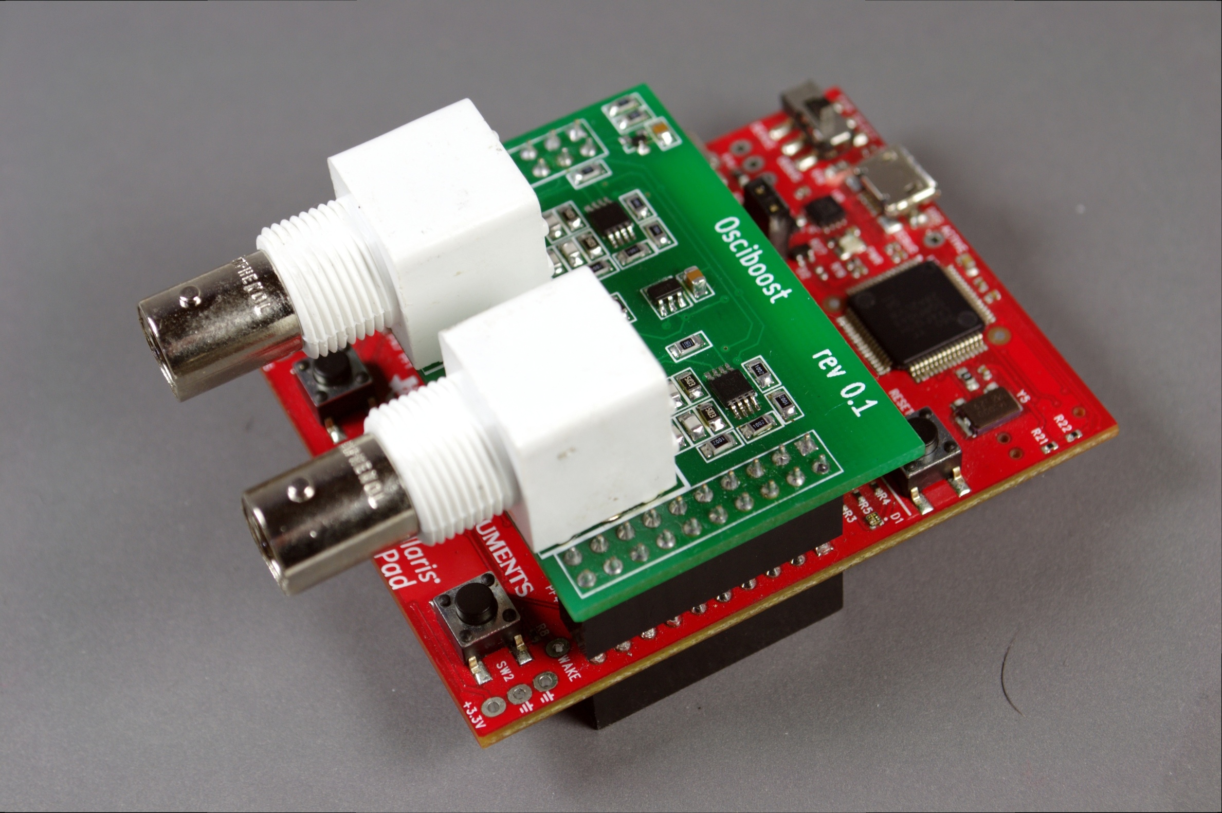
Another week bites the dust, and coffee supplies are running low. The swarm of zombies is vultureprog_temprestless, but they seem to be active mostly at night. The barricaded windows are holding up well for the time being. I can venture small distances during the day, but not far enough to reach other survivors.  I was able to recover a package from the mailbox this week. Its unannounced appearance is still a mystery, but its contents are most enthralling in this forlorn aeon. I was able to use the waterblocks in the package to reduce my heat signature. There are fewer of THEM trying to break through the barricades. Last night, the leader of the pack did not disturb my hiding place. I don’t know if help will ever come, but I owe it. I owe it to myself, and to the flight engineers. I do not know if they survived, but I owe it to them to finish the flight plans. We must leave this planet.

If you are listening to this transmission, you are a survivor. I have spent this last week in improving the flight plans; I have annotated and documented them in glorious detail. Get them here:

$ git clone git://git.qiprog.org/qiprog.git
$ git clone git://git.qiprog.org/vultureprog.git

 How QiProg works

QiProg was originally designed to be a pure USB protocol, specialized in driving flash chip programmers. Peter Stuge’s original QiProg specification is just that: a USB protocol. But as Peter suggested, once that protocol is converted into API calls, it stops being a protocol, and becomes a full-featured API. It’s amazing how each USB control request can be mapped to one and just one API call. Most USB dependencies become invisible in the API, with a very limited number of exceptions, where the dependence on USB could be inferred from the size of the data structures. Even in these limited cases (hint: there are exactly three), the dependency on the USB bus can trivially be abstracted away. My original reaction was to modify the spec to remove them, but that patch now sits lonely on a forgotten github branch.

QiProg initialization

Initializing the QiProg logic is a very boring boilerplate operation. Luckily, this can be done with just one or two API calls. In fact, I have only included three functions to take care of this. They can create a context, free a context, or set the verbosity of debug messages. That’s it: the very standard boilerplate.

QiProg device discovery

The discovery phase is yet again, boilerplate, albeit a very smart suggestion from Peter. With a single, lightweight call,  qiprog_get_device_list(), QiProg scans all devices and presents them in a flat list. This gives us a bunch of qiprog_device pointer. The qiprog_device pointers are at the heart of QiProg. The public API only presents them as pointers, as opaque as the dictionary allows.

Once we have a device pointer, we can try to open the device, ask the device what it can do, and decide whether or not to hire it. Once we hire a device, the real fun begins

The QiProg core

Remember how I said QiProg devices are presented as opaque pointers? This makes them full-fledged objects. Anytime we want to do anything with the device, we have to perform a device operation. This is exactly where the core come is. It makes sure that the operation is dispatched to the correct handler (more on that later), and makes sure that we don’t crash because of programming mistakes. If I had written QiProg in C++, I would have made the qiprog_device an abstract class, and would have hidden the derived classes and their constructors away from the API.

So, what’s in the core?

qiprog_do_action_x(device, action_parameters...);

That’s about it. action_x can be any of the actions in the original QiProg specification. While it might seem that a _lot_ of logic is needed to make this happen, the core is actually ludicrously lightweight.

Inside the core

QiProg is designed to handle more than just USB programmers. This brings the need for different code paths for each class of devices. Internally, QiProg implements a “driver” for each class. This driver is a structure with function pointers. QiProg asks each of these drivers to scan for available devices, and append them to a context-global device list. This is the exact list we get with qiprog_get_device_list().

So, back to the core. Since the drivers are invisible to the outside world, we can’t get those function pointers. This is the job of the core. The core dereferences the device pointer, and sanity-checks it. This sanity checking removes most boilerplate from the application. And now the magic: each device stores a pointer to its associated driver. All the core has to do is dereference the driver and call the appropriate function with the device as the parameter.

Each device gets a void pointer to store private data. The driver decides what to store there and how to use it. That is sufficient to carry all necessary context information, and why the device pointer is passed to each member of the driver. Since there is no need to look up context information, the core is essentially an O(1) operation. This is the reason we can run the core on the embedded QIProg device.

The hidden QiProg core

Yes, QiProg is running on the VultureProg device as well, not just the host. We don’t care about discovery, or any function that does not need a qiprog_device. Those steps can be handled by standard USB requests; all information is in the USB descriptors. The situation, once again, turns interesting when we have a qiprog_device. VultureProg has a qiprog_device as well (and it can have several).

From USB to the core

Any USB transaction will come in through some sort of hardware-specific channel. It’s the nature of the beast. So, the first thought is: “OK, let’s write a bus IO, hook it into the USB handler, and be done”. However, we can make our USB dispatcher forward control requests to QiProg. And this is where a little file that never seems to be included in the build comes in. qiprog_usb_device.c is never compiled in host code, but is our bridge to QiProg on VultureProg devices. It takes USB requests, and forwards them to a real QiProg driver.

Ok, let’s pause for a second:qiprog_api

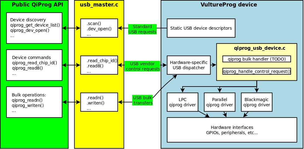
Yes, we run QiProg drivers inside the little Cortex-M processor, and with QiProg drivers comes the slick QiProg core. There are a few more tricks we use for making several drivers use the same hardware, but they are far too technical. For the curious, I have to words: “doxygen documented”.

VultureProg: Meet the contenders

cable_salad

Wow! It’s the weekend already. Where was this last week? With the first week of the 12 weeks of GSoC already gone, I think the time to panic has arrived.  Looking back on my original proposal, I realized I have given anyone interested definitive proof I am indeed and indubitably insane. I have offered to design and build hardware, gift it with a fully functional and versatile firmware, write the software to control it, and integrate the functionality into flashrom. To the untrained eye, the last statement resembles a description of four separate GSoC projects. Here at coreboot, that’s all in a day’s work, with enough time for lunch.

Continue reading VultureProg: Meet the contenders

A biology laboratory: Dissecting the LPC bus

I feel nostalgic over PLCC ROMs. They are by far the most practical way to store firmwarerxfne2. They replaced the huge 32-pin DIP chips whose pins were very likely to bend or break off as one tried to remove them from the socket. The first board I ever tried to hack on had a PLCC32. After I bricked the board, a friend was able to track down Cristi Măgherușan in Cluj. When I went to meet Cristi in the hope that he might be able to salvage the board, I carried the chip in a little plastic bag in my pocket. He was never able to flash it, but this little detail is of less importance. What matters is that LPC interfaces were most popular in PLCC32 chips, and this is the interface I will be primarily focusing on.

Why bother with LPC in the first place?

Parallel buses were the norm in the 80’s and 90’s. The idea is simple. Have a number of data lines, usually 8, 16, or 32, a clock, and maybe handshake signals. When I say the idea is simple, I mean it literally: the hardware is very simple. The clock is fed straight to the flip-flops which latch the data on the bus. The handshake signals also feed straight into logic gates that control the state of the pins (inputs, or outputs), etc. There is no extra logic needed to figure out when to do what on the bus. Having simple buses saved a lot of silicon real estate for the intended purpose of an integrated circuit.

As transistors got smaller, they got faster, but the laws of Physics did not change. Electromagnetic waves in a metal travel at the speed of light (well, a little slower when you consider electrodynamics effects). Since the information is carried on the wavefronts, we really don’t care how fast electrons are moving. If a signal is 10 centimeters longer, it will arrive 0.33 nanoseconds later. On an 8MHz ISA bus (125ns cycle time), this delay is insignificant. The little physics policemen do not stop here, however. Wires are nothing but little series inductors radiating energy to ground planes and other wires like little parallel capacitors. It takes tiny amounts of energy to energize a wire to the right voltage. This process takes a tiny amount of time, usually a few nanoseconds. If we’re lenient, and allow 12ns , add the travel time to our sloppily routed signal, and it takes 12.33 ns from the time we drive the signal to the time it reaches its destination at the correct voltage. That’s 1/10th of our ISA cycle time. To get around this, simple buses drive the data on one edge of the clock, and sample it on the other edge.

Fast-forward to the 90’s and the 33MHz PCI bus. If we allowed 12 ns for any signal to rise, and 12 ns for it to fall, we would already waste 24 ns of the 33 ns allotted for each cycle. We get a tiny 5 ns window to latch the correct data. All of a sudden, routing signals to reduce inductance and capacitance, and match their travel times becomes a lot more important… and expensive. ISA is downgraded to a second-class citizen: It doesn’t make sense to route a high number of additional signals for a low-speed bus, and it doesn’t make sense for low-speed components to move to more expensive PCI silicon. This is the gap the LPC bus fills.

The LPC

LPC eradicates ISA for a 4-bit, 33MHz bus, a clock, and a handshake signal. The 33MHz clock is not an accident. Rather it is meant to be derived directly from the PCI clock. The signaling bandwidth of 16.5 MB/s (33MHz * 0.5 Bytes) is very close to ISA’s 16MB/s (8MHz * 2 Bytes). Handshakes are handled through the data pins, though they require very little silicon logic.

Let’s have a look at what LPC brings us:

  • LAD[3:0] – 4-bit data
  • LCLK – 33MHz clock
  • #LFRAME – Start of frame handshake

Signaling and handshakes happen within a frame. A frame is a predefined sequence of handshakes and data transfers. Somewhere within the frame we transfer the actual data byte. Let’s take a look at what a typical frame looks like:error_in_lpc

A bit cryptic until we put some meaning into the signaling:

error_lpc


Aaah! Much better. Here’s what happens:

  • #LFRAME starts a new frame.
  • LAD is at 0x0, which indicates the start of a cycle for a target.
  • In the next cycle, we put 0x4 on the LAD pins. This indicates we want to start a memory read.
  • The next 8 cycles are the memory address: 0xFFBC0000. This is the JEDEC address for reading the manufacturer ID.
  • Next, we start a turnaround cycle (TAR) which transfers the control of the bus to the target.

The TAR cycle is supposed to last two clocks. We drive the pins high during the first clock, then float them with a pull-up in the next clock. The chip is supposed to wait until the third clock to send us a SYNC (LAD[3:0] driven low). And the first problem: the SST 49LF080A is guilty of violating the LPC spec. It does not wait for the third clock to send the SYNC. It most likely implements an internal delay, and completely ignores the TAR cycle. It’s these sort of unexpected problems that have prompted me allocated a lot of time in my GSoC project to figuring out how to master the LPC bus. This problem will most likely require ARM assembly blackmagic to more closely match the timing to that of a 33MHz clock.

After the skipped clock, everything looks fine though (If one clock early can really be considered “fine”). We get 0xBF in the data cycle, which is SST’s manufacturer ID. Success!

Launch control and a brief test-flight

superboostedLast time, I promised I would prepare you for a short test-flight. We won’t go into a full orbit, but we will turn on the thrusters, launch, and land safely. This is a real mission. We will actually launch the Stellaris into firmware low-orbit.

The Toolchain

We need a tool to transform the flight plans into something the Stellaris can understand. I will call this The Toolchain. Having a good toolchain (compiler and supporting libraries) will save us a lot of trouble. Well, it will save you a lot of trouble; I already have a decent toolchain. At the very least, the toolchain should be aware of the following:

  • Hard-float “-mfloat-abi=hard -mfpu=fpv4-sp-d16” compiled libraries
  • A minimal C library
  • libnosys

I will be using the summon-arm toolchain, but any arm-none-eabi will do. I won’t go over the details of setting up this or that toolchain. The options are plentiful.

The Debugger

We need a tool to monitor the Stellaris in-flight, and solve any potential issues. Let’s call this tool The Debugger. I will be using OpenOCD since it works for me (TM). You will need version 0.7.0 or newer, with ti-icdi support enabled. I will say no more.

HINT: if you need to build it from source, pass “–enable-maintainer-mode –enable-ti-icdi” to the configure script.

The Flight Plans

This is the fun part. I have been working since last year on Flight Plans for the Stellaris Launchpad. Courtesy of flight engineer Peter Stuge, the flight plans are available on the QiProg website (more on that later).

OK, let’s get them:

$ git clone git://git.stuge.se/vultureprog.git
$ cd vultureprog

And the flight plans for the subsystems:

$ git submodule init
$ git submodule update

Now it’s time to choose our mission:

$ git checkout 841ba3460767eefc2c744ec03c37e7e383cd8485

Now that we have everything we need:

$ make

This should get the Flight Plan primed and ready.

The Launch

Assuming everything went fine so far, we are go for launch. Prepare your Stellaris Launchpad. When you are ready for launch:

$ make flash -C boards/lm4f/stellaris-ek-lm4f120xl/

WARNING! Do not look directly in the thrusters (LEDs) of the Stellaris. Thrusters are operated at full power and may cause temporary loss of vision.

If you see the thrusters (LEDs) alternating, then launch was a success. Congratulations! During the test flight, you can try pressing the buttons on the Stellaris (HINT: they do something).

The Announcements

Peter Stuge has been kind enough to set up a website for QiProg on his own time. It’s http://qiprog.org . Stable code will be pushed to the git repositories at http://git.qiprog.org. Development will be kept on github for the time being, on my vultureprog repository. I will only be pushing stable updates to qiprog.org.

That’s all for now. Mission accomplished.


Hello world

Hello World! I am Alexandru Gagniuc, and I’m a free software addict.

superboosted2

I got involved in coreboot in early 2011. I had an old VIA board and just thought I’d try coreboot on it. What could go wrong with an unsupported board? I ignored the “everything” part, and nothing went wrong. I never finished that port, but that’s of less relevance. I learned “how things are done around here”. Besides starting to make small contributions here and there, I was also lucky enough to catch an NDA with VIA and a free EPIA-M850 board. The only thing supported on that board was the superio. Today, we can initialize DDR3 memory and boot Linux with it.

My journey was perilous. I have met a great number of wonderful people along the way. Actually, that’s where I learned most of what I know. My only useful skill when I arrived was knowing how to read C syntax. I have since contributed to a modest number of other projects, most notably sigrok and libopencm3 (I’m the same guy that added support for LM4F there). I just like making hardware come to life, it seems.

This summer, I will be bringing you a tool to unlock your bricked LPC and FWH flash chips. I need a break from needing to program 30 years of history, and needing to deal with thousands of registers in several different IO and memory spaces. I’ve chosen Cortex-M as my operating table. No port IO, no configuring memory regions, no interrupt handlers, no memory initialization, no “any of the one million things that can silently break”. Everything is memory-mapped and the number of registers is so insanely small, that it makes sense to #define them all. It’s small, it’s readable, it’s not confusing. It’s beautiful. It’s the best coding vacation anyone can take from coreboot.

I will use a Stellaris Launchpad as my patient. For anyone coming late to the game, the new name is Tiva C Launchpad. I’ll use the Stellaris because

  • it sounds a lot cooler than “Tiva C”
  • the name actually fits well next to “Launchpad”
  • I was able to snatch a couple of them last year for $5 a piece.
  • The picture at the top would not look as cool if it were a “Tiva C”

I’ll turn the innocent looking red slab into a mean lean, programming machine. We’ll start with LPC. Emulating a 33MHz 4-bit bus should be fun (not counting the obscene cost of coffee, and red eyes due to sleepless nights). I didn’t say it will be easy, but as Jimmy McMillan once said, “the fun is too damn high!”

Next time, I’ll tell you how to set up the development environment, and how to put some firmware on the board.