[GSoC] Coreboot Coverity, weeks 8-10

Hello everyone! Coverity has come back online again after its long upgrade, and with it a pile of new scan issues (over 100). I put aside a week to fix all the new issues in parts of the code base I had already worked through, and then spent the next two weeks finishing soc and the Cavium vendorcode. Referring to the overview page, there are now 300 scan issues left in the code base. While a considerable number, this consists almost entirely of patches still going through review, vboot, and the AMD vendorcode — everything outside of this is done. At this point, the plan at the beginning of the summer was to continue working on the AMD vendorcode, but after discussing with my mentors we have decided to do something else. The AMD vendorcode is extremely dense, and with the upcoming deprecations in 4.11 it may not be around for much longer. The plan now is to work on vboot and the recently resurrected scan page for flashrom.

Anyway, enough with the boring schedule stuff. I finally got around this week to wiping the ME on my T500, and like last time it was a lot more involved than I expected. Onwards!

The Intel Management Engine (ME) is an autonomous coprocessor integrated into all Intel chipsets since 2006. Providing the basis for Intel features such as AMT, Boot Guard, and Protected Audio Video Path (used for DRM), the ME has complete access to the system memory and networking. The ME runs continuously as long as the system has power, even if the computer is asleep or turned off, and on systems with AMT can even be accessed remotely. Naturally, this is an incredible security risk. On modern systems it is impossible to disable the ME completely, since any attempt to do so will start a watchdog timer that will shutdown the computer after 30 minutes. However, in older chipsets (such as the one in the T500), no such timer exists, allowing attempts to disable it entirely.

The ME firmware is located in the SPI flash chip, which is divided into multiple regions. Using the coreboot utility ifdtool, we can analyze a dumped ROM to check the regions in the layout along with their offsets within the flash image.

$ ifdtool -f layout.txt factory.rom
File factory.rom is 8388608 bytes
Wrote layout to layout.txt
$ cat layout.txt
00000000:00000fff fd
00600000:007fffff bios
00001000:005f5fff me
005f6000:005f7fff gbe
005f8000:005fffff pd

These regions are as follows:

  • Intel Flash Descriptor (fd) – Describes the layout of the rest of the flash chip, as well as various chipset configuration options. This blog post by Alex James has further information about the IFD.
  • BIOS (bios) – Contains the factory BIOS. Normally this is the only part of the flash chip that you overwrite when installing coreboot.
  • Management Engine (me) – Firmware for the ME coprocessor, including a kernel (ThreadX on older models, MINIX 3 on newer ones), as well as a variety of other modules for network access and remote management.
  • Gigabit Ethernet (gbe) – Configuration for the Gigabit Ethernet controller, including the system’s MAC address.
  • Platform Data (pd) – Other miscellaneous data for the factory BIOS, which coreboot doesn’t use.

The IFD also contains read and write permissions for the rest of the flash chip, which we can analyze using ifdtool.

$ ifdtool -d factory.rom
...
FLMSTR1:   0x1a1b0000 (Host CPU/BIOS)
   Platform Data Region Write Access: enabled
   GbE Region Write Access:           enabled
   Intel ME Region Write Access:      disabled
   Host CPU/BIOS Region Write Access: enabled
   Flash Descriptor Write Access:     disabled
   Platform Data Region Read Access:  enabled
   GbE Region Read Access:            enabled
   Intel ME Region Read Access:       disabled
   Host CPU/BIOS Region Read Access:  enabled
   Flash Descriptor Read Access:      enabled
   Requester ID:                      0x0000
...

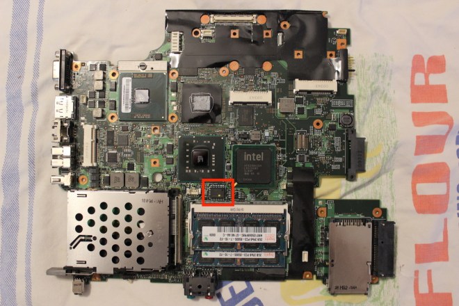
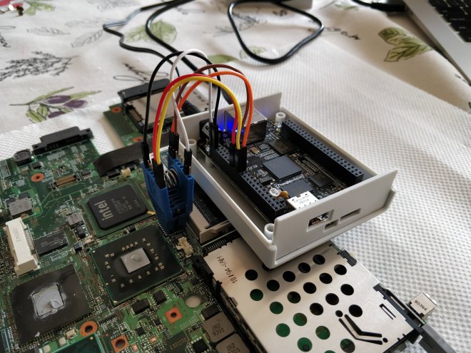
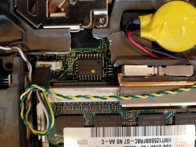
Unfortunately, ME write access is disabled for the host CPU, which prevents us from overwriting it using an internal flash — we’re gonna have to get out the external programmer. If you recall from last time, accessing the SOIC of the T500 required a laborious process of extracting the motherboard from the case, so this time I cut a little hole in the frame to make flashing easier. As it turned out, having this easy access port was very handy.

The old way.
The new — a bit hacky, but it works.

After reading back the ROM image, I decided to use try using me_cleaner, a tool for partially deblobbing the ME firmware on newer laptops, and for mine removing it entirely. Following the instructions for an external flash, we use the -S flag to clean the firmware.

$ python me_cleaner.py -S -O coreboot-nome.rom coreboot-orig.rom
Full image detected
Found FPT header at 0x1010
Found 13 partition(s)
Found FTPR header: FTPR partition spans from 0xd2000 to 0x142000
ME/TXE firmware version 4.1.3.1038 (generation 1)
Public key match: Intel ME, firmware versions 4.x.x.x
The meDisable bit in ICHSTRP0 is NOT SET, setting it now…
The meDisable bit in MCHSTRP0 is NOT SET, setting it now…
Disabling the ME region…
Wiping the ME region…
Done! Good luck!

After wiping the image, we can use ifdtool again to see that the ME region has been completely erased.

00000000:00000fff fd
00600000:007fffff bios
005f6000:005f7fff gbe
005f8000:005fffff pd

While this is the most sure-fire way to ensure the ME has been disabled, it’s not perfect — on boot the ME coprocessor will still attempt to read from its firmware in the flash region, and finding it not there will hang in an error state. However, it has been discovered through reverse engineering that Intel has incorporated various bits into the IFD that will disable the ME soon after boot. (One of these, the High Assurance Platform “HAP” bit, was incorporated at the request of the US government, which also understands the security risks of an unfettered ME.) For my laptop, this consists of setting two bits in the ICHSTRP and MCHSTRP, which me_cleaner does by default. After enabling this, the ME should gracefully shutdown after boot, which hopefully will cause the fewest system stability issues.

Finally after all that, let’s use ifdtool again to unlock all regions of the flash chip, which should ideally negate the need of ever doing an external flash again.

$ ifdtool -u coreboot-nome.rom

Let’s write it! Unlike last time we write the entire image, not just the BIOS region.

$ flashrom -p linux_spi:dev=/dev/spidev1.0,spispeed=4096 -w coreboot-nome-unlock.rom

Now the moment of truth. After hitting the power button … nothing. Gah.

Well, not exactly nothing. The screen doesn’t turn on, but the CD drive is making noises, so it’s not completely dead. Hmmm, let’s try again, but this time only setting the disable bits without wiping the ME region. This can be done using the -s flag of me_cleaner (which incidentally has a bug that required a small patch).

$ python me_cleaner.py -s -O coreboot-nome.rom coreboot-orig.rom

Reflashing again … same problem. Nothing.

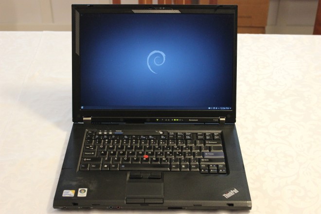
Not completely sure what to do and worried that the ME was actually needed to boot, I decided to flash a pre-compiled Libreboot image on the laptop, which has the ME disabled out of the box and should hopefully Just Work. … And it did! The computer booted gracefully into the OS with no glitches or stability issues that I could see. Perfect. So disabling the ME is technically possible, but how exactly do I do it? Asking around a bit on IRC, I was directed to the coreboot bincfg utility, which is capable of generating an ME-less IFD from scratch. Following this similar guide for the X200, I was able to piece together a complete ROM.

First, we need to generate a new IFD. The bincfg directory contains configuration files for the X200, which we can fortunately re-use since the T500 has the same controller hub.

$ bincfg ifd-x200.spec ifd-x200.set ifd.bin

This IFD comes with only three regions, and has the ME disable bits set by default.

00000000:00000fff fd
00003000:007fffff bios
00001000:00002fff gbe

There are also configuration files for generating a new GbE region, but that requires certain fiddlings with the MAC address that I don’t know how to do — for now we can re-use the GbE from the old ROM, using ifdtool to chop it out.

$ ifdtool -x coreboot-orig.rom
File coreboot-orig.rom is 8388608 bytes
  Flash Region 0 (Flash Descriptor): 00000000 - 00000fff
  Flash Region 1 (BIOS): 00600000 - 007fffff
  Flash Region 2 (Intel ME): 00001000 - 005f5fff
  Flash Region 3 (GbE): 005f6000 - 005f7fff
  Flash Region 4 (Platform Data): 005f8000 - 005fffff
$ mv flashregion_3_gbe.bin gbe.bin

Next, we place the IFD and GbE regions in a blobs directory in the root of the coreboot tree, and then direct the build system to use them when generating an image. Here are the menuconfig settings:

General setup ---> [*] Use CMOS for configuration values
              ---> [*] Allow use of binary-only repository
Mainboard ---> Mainboard vendor ---> Lenovo
          ---> Mainboard model ---> ThinkPad T500
          ---> Size of CBFS filesystem in ROM (0x7fd000)
Chipset ---> [*] Add Intel descriptor.bin file (blobs/ifd.bin)
        ---> [*] Add gigabit ethernet configuration (blobs/gbe.bin)
        ---> Protect flash regions ---> Unlock flash regions
Devices ---> Display ---> Linear "high-resolution" framebuffer
Payloads ---> Add a payload ---> SeaBIOS
         ---> SeaBIOS version ---> master

Note that since the ME and Platform Data regions have been deleted from the new layout, we can expand the CBFS to the entire bios size — 0x7fd000 bytes, nearly the entire flash chip. This will allow in the future installing bigger and more interesting payloads, such as GRUB or LinuxBoot.

Finally, I wrote this new image to the flash chip. It worked. Huzzah!

After installation, we can check the status of the ME using intelmetool.

$ sudo intelmetool -m
Can't find ME PCI device

Perfect.

[GSoC] How to Run C Code in Bootblock Stage for QEMU/AArch64

Hi, I’m Asami. My project “adding QEMU/AArch64 support to coreboot” is making good progress. I’ve almost done to write porting code and I’m now writing a new tool to make a FIT payload for QEMU/AArch64. Here is my CL. In this article, I’m going to talk about how to run C code in the bootblock stage.

The way to run C code before DRAM has been initialized is various in the coreboot project. The most famous and used in the x86 system is known as the Cache-As-Ram (CAR). CAR can be set up by 1. enable CPU cache 2. enable the ‘no eviction’ mode 3. change cache mode from write-through to write-back. ‘No-eviction’ means that the CPU doesn’t write any data to DRAM as long as the size of data is less than the CPU cache. Then, you can get all the data from the CPU cache. The implementation for CAR is src/cpu/intel/car/non-evict/cache_as_ram.S.

Another way to run C code especially implemented in ARM system is relocating the bootblock code to SRAM. System on a Chip (SoC) has an ARM CPU and often includes SRAM as a cache. For example, QEMU VExpress machine has SRAM is located at 0x48000000 that we can know in qemu/hw/arm/vexpress.c#L120.

However, what should the system that doesn’t have SRAM do? My target machine, QEMU virt machine, doesn’t have SRAM according to the implementation of qemu/hw/arm/virt.c. In this case, should we initialize DRAM earlier?

The answer is No but it’s only for my project. Because QEMU is not actual hardware so DRAM already works. I just need to relocate the bootblock code to DRAM directly. I believe that other ARM systems that have no SRAM should initialize DRAM earlier.

You can see the relocation code in bootblock_custom.S under review. https://review.coreboot.org/c/coreboot/+/33387

[GSoC] Coreboot Coverity, weeks 5-7

Hello again! It’s been three weeks since my last post (well, one of those weeks I was on vacation, so more like two weeks), so there are many many updates to write about. If you recall from my last post, Coverity has been down for maintenance, so I started looking around for other things to do. Here is a list of some of the highlights:

  • Coverity isn’t the only static analyzer we use – coreboot also runs nightly scans using the Clang Static Analyzer, an open source tool from the LLVM project. The results from these scans aren’t as detailed as Coverity and unfortunately contain many duplicates and false positives, but I was able to submit patches for some of the issues. Usability of the analyzer is also still somewhat limited, since we have no way of recording fixes for past issues or ignoring false positives. (A framework like CodeChecker might be able to help with this.)
  • coreboot will (hopefully) soon be (almost) VLA free! Variable length arrays (VLAs) were a feature added in C99 that allows the length of an array to be determined at run time, rather than compile time. While convenient, this is also very dangerous, since it allows use of an unlimited amount of stack memory, potentially leading to stack overflow. This is especially dangerous in coreboot, which often has very little stack space to begin with. Fortunately, almost all of the VLAs in coreboot can be replaced with small fixed-sized buffers, aside from one tricky exception that will require a larger rewrite. This patch was inspired by a similar one for Linux, and is currently under review.
  • Similar to the above, coreboot will also soon be free of implicit fall throughs! Switches in C have the unfortunate property of each case statement implicitly falling through to the next one, which has led to untold number of bugs over the decades and at least 38 in coreboot itself (by Coverity’s count). GCC however recently added the -Wimplicit-fallthrough warning, which we can use to banish them for good. As of this patch, all accidental fall throughs have been eliminated, with the intentional ones marked with the /* fall through */ comment. Hopefully this is the last we see of this type of bug.
  • coreboot now has a single implementation of <stdint.h>. Previously, each of the six supported architectures (arm, arm64, mips, ppc64, riscv, and x86) had their own custom headers with arch-specific quirks, but now they’ve all been tidied up and merged together. This should make implementing further standard library headers easier to do (such as <inttypes.h>).
  • Finally, many coreboot utilities and tools such as flashrom, coreinfo, nvramtool, inteltool, ifdtool, and cbmem have stricter compiler warnings, mostly from -Wmissing-prototypes and -Wextra. Fixing and adding compiler warnings like these are very easy to do, and make great first time contributions (-Wconversion and -Wsign-compare in particular can always use more work).

That’s it for this week! Thankfully Coverity is back online now, so expect more regular blog posts in the future.

[GSoC] Debug Bootblock Stage for ARMv8 on QEMU

Hello again, I’m Asami. I’ve just finished 4 weeks as a GSoC student. I’m currently debugging the implementation of my main project, which is adding QEMU/AArch64 support. I can see nothing output right now when I start a QEMU with the coreboot.rom that has my implementation. It means there is something wrong before a hardware initialization has finished. In this article, I’m going to talk about what I found while debugging the bootblock for ARMv8.

Code Path of Bootblock Stage

The bootblock is executed just after CPU reset and it is almost written by assembly language. The main task is to set up a C-environment. The basic code path for ARMv8 from the beginning the bootblock to the romstage is:

  1. _start() at src/arch/arm64/armv8/bootblock.S
  2. arm64_init_cpu() at src/arch/arm64/armv8/cpu.S
  3. main() at srclib/bootblock.c
  4. run_romstage() at src/lib/prog_loaders.c
  5. prog_run() at src/lib/prog_ops.c
  6. arch_prog_run() at src/arch/arm64/boot.c
  7. main() at src/arch/arm64/romstage.c // The entry point of the romstage

You can use your custom _start function instead of the common _start function by CONFIG_BOOTBLOCK_CUSTOM=y and adding bootblock-y += bootblock_custom.S which is your custom assembly file.

The Reason Why Execution Stopped inside arm64_init_cpu()

I found that an execution stopped inside the arm64_init_cpu function for some reason. The line that has some problem is mrs x22, sctlr_el3 . MRS instruction can read a system control register and store the value into a general purpose register. So this line means to store the value of SCTLR_EL3 into the X22 register.

According to the “ARM Architecture Reference Manual ARMv8, for ARMv8-A architecture profile”, the purpose of SCTLR_EL3 is

Provides top level control of the system, including its memory system, at EL3. This register is part of the Other system control registers functional group.

Also, SCTLR_EL3 is accessible only from EL3 mode. EL3 is the highest privileged mode that a low-level firmware, including the secure monitor, works on it.

Next, I checked the current mode via mrs x0, CurrentEL. CurrentEL is a register that holds the current exception level. The result of CurrentEL was 0x04, which means the program works on EL1 mode. EL1 is the mode that an operating system kernel typically described as privileged. I didn’t have the right to access SCTLR_EL3. That’s why an execution stopped.

Ideas to Solve EL3 Issue

I considered 2 solutions:

  1. Use only EL1 registers
  2. Run QEMU in EL3

Firstly, I tried to use only EL1 registers. I replaced arm64_init_cpu with arm64_init_cpu_el1 that is a new function I created. Then I replaced SCTLR_EL3 with SCTLR_EL1 and TLBI ALLE3 with TLBI VMALLE1. It seems to work well but still, there was nothing output.

Secondly, I tried to run QEMU in EL3 that is enabled by -machine flag. QEMU can work on EL2 with -machine virtualization=on and EL3 with -machine secure=on to enable EL3. The following command works well for me.

$ qemu-system-aarch64 -bios ./build/coreboot.rom -M virt -cpu cortex-a53 -nographic -smp 1 -machine secure=on

My mentor Raul told me the second solution. Thank you so much!

[GSoC] Coreboot Coverity, week 4

Hello again! If you recall from my last post, the schedule this week is to fix the issues in northbridge/via and southbridge. However, Coverity is going through a major internal upgrade, and so the issue tracker has been offline all week. Luckily though I was able to fix most of these issues last week, so assuming the upgrade finishes soon I won’t be behind schedule. In the mean time, I decided to try flashing coreboot onto my T500, since the last component I was waiting for arrived last week. Here is a little mini-guide to my (sometimes harrowing) flashing experience.

Supplies

  • ThinkPad T500
  • BeagleBone Black
  • 5V 2A power adapter for the BBB
  • Jumper Wires
  • Pomona 5252 Test Clip
  • Atheros AR9462 Wireless Card

Updating the EC

It is generally recommended to update the embedded controller firmware before flashing coreboot, which can only be done during a Lenovo BIOS update. (Unlike Chromebooks, ThinkPads unfortunately do not have open source EC’s.) I was able to find a copy of the latest BIOS on the Lenovo EOL Portal, and attempted to perform an update … which froze and crashed halfway through. Uh oh. This is OK, as long as I don’t restart the computer I can just try flashing it again, right? Wrong! The next time I tried it Windows ran into a fatal error and decided to force a restart for me (gah!). Upon booting it up again, I was met with absolutely nothing, because the screen wouldn’t even turn on. More than a little concerned that I had bricked it, I searched through online forums until I stumbled across the Crisis Recovery tool. Apparently, old ThinkPads have a method to force-update the BIOS from an external USB stick or floppy (if you have one of those lying around). The recovery tool had to be run in Windows XP Service Pack 3 emulation mode, and seemed to format the USB correctly. My ThinkPad wasn’t so impressed, and obstinately refused to recognize the stick. As a last hope, I asked around on IRC what to do, and Nico Huber informed me that the ThinkPad was likely not dead, and that I could just proceed with flashing coreboot anyway. Well, here goes nothing.

Building Coreboot

So we’re going to flash coreboot, but what options do I pick when compiling it? I scoured around the internet to find tutorials for flashing coreboot onto a T500 and other related ThinkPads, but they all recommended different options, sometimes contradictory. Hmmmm. Once again going back to IRC, Angel Pons helped me configure a very minimal build.

General setup ---> [*] Use CMOS for configuration values
              ---> [*] Allow use of binary-only repository
Mainboard ---> Mainboard vendor ---> Lenovo
          ---> Mainboard model ---> ThinkPad T500
Devices ---> Display ---> Linear "high-resolution" framebuffer

Now, the T500 is a very special laptop, in that it can run coreboot without any binary blobs at all. However, I decided to enable microcode updates anyway, since they provide important stability improvements (like not crashing). This laptop also comes with an Intel ME which can be completely wiped, but I decided to leave that for later. (Now that I know coreboot works, there will be a follow-up post in several weeks when I do that.)

Disassembly and Flashing

Like most laptops, the flash IC of the T500 is locked from the factory, and requires an initial external flash to install coreboot (afterwards, subsequent flashes can be done internally). This requires disassembling the laptop to access the SOIC-16, which is buried in the bowels of the T500 case and requires a complete tear-down to access. The Libreboot T500 page gives you a feel for the amount of work required to extract the motherboard, which along with the hardware maintenance manual I referred to extensively.

SOIC-16 highlighted in red

With the motherboard extracted from the case, the next step is to attach the Pomona 5252 to the SOIC-16 and jumper it to the BBB, which was all made very easy by this X200 guide. Somewhat blithely following the previous guide, I set up an old ATX PSU to provide 3.3v to the flash chip. However, whenever I connected it to the test clip, it would always power itself off. Strange. Going back to IRC, Nico informed me that this is in fact A VERY BAD AND DANGEROUS THING TO DO. THE INTERNET IS LYING – DO NOT USE AN ATX PSU, YOU COULD FRY YOUR MOTHERBOARD! Oops. After puzzling over how to provide enough power to the chip without the PSU, Patrick Rudolph chimed in that a) the T500 motherboard is basically indestructible (whew!), and b) the flasher itself should be able to provide enough power. Hooking the 3.3v cable into the BBB instead, I tried reading the flash chip.

$ flashrom -p linux_spi:dev=/dev/spidev1.0,spispeed=512
(a bunch of output that I forgot to write down)

It works! Even with a bricked Lenovo BIOS, it is still recommended to keep a backup, so next we read the old factory ROM.

$ flashrom -p linux_spi:dev=/dev/spidev1.0,spispeed=512 -r factory.rom

Do this three times with three distinct images, and compare their SHAsums to make sure they are all identical (otherwise the connection might be faulty). If they all match, keep one as a backup.

Now the moment of truth: writing coreboot.

$ flashrom -p linux_spi:dev=/dev/spidev1.0,spispeed=512 --ifd -i bios -w coreboot.rom

Note that because I left the ME as-is, it is important to only flash the BIOS region, not the entire chip.

Reassembly and Testing

Sadly, no instant gratification here – I had to reassemble half the laptop before I could test booting it up. However, after doing so and gingerly pressing the power button, I was greeted by the lovely SeaBIOS boot menu. It actually worked! Huzzah! Finishing reassembly, I replaced the factory Intel wireless card with an Atheros AR9462, which can run without any binary firmware. After installing Debian, I now have a laptop running completely free and open source software, all the way from the BIOS up (well, except for the ME, but I’ll fix that later).

T500 running coreboot and Debian 9

For the final icing on the cake, here is a fresh board status report for the T500. Many thanks to everyone who helped me in this process.

[GSoC] Common Mistakes for Beginners

Hello everyone. I am Asami and a student for this year’s GSoC project. My project is adding a new mainboard QEMU/AArch64 to make it easier for coreboot developers to support new boards for ARMv8. I’ve already written a small patch to enable building a sample program with libpayload for ARM architecture. Also, I’ve read the implementation of coreboot (main code path) for ARMv7 and QEMU (qemu/hw/arm/vexpress.c). Now, I just created a new CL for my main project and I started to read the implementation of the target machine of AArch64 (qemu/hw/arm/virt.c).

In this article, I’m going to talk about my mistakes when I developed coreboot. I hope it helps for beginners of coreboot development. The target board is QEMU/ARM and the CPU is ARMv7.

“ERROR: Ramstage region _postram_cbfs_cache overlapped by: fallback/payload”

I faced this error when I built coreboot.rom for QEMU/ARM with the coreinfo which is a small informational payload for coreboot. The cause is that the coreinfo doesn’t support ARM architecture and then the payload is compiled as a 32-bit x86.

Make sure that your payload is your target architecture. You need to use other executable files instead of the coreinfo when you want to use architectures other than x86. We provide the libpayload which is a small BSD-licensed static library.

The details of the error is:

$ make
...(omitted)....
W: Written area will abut bottom of target region: any unused space will keep its current contents
CBFS fallback/romstage
CBFS fallback/ramstage
CBFS config 
CBFS revision
CBFS fallback/payload
INFO: Performing operation on 'COREBOOT' region...
ERROR: Ramstage region _postram_cbfs_cache overlapped by: fallback/payload
Makefile.inc:1171: recipe for target 'check-ramstage-overlaps' failed
make: *** [check-ramstage-overlaps] Error 1 

“ERROR: undefined reference to ‘_ttb'” and “ERROR: undefined reference to ‘_ettb'”

This errors might happen when you build coreboot.rom by `make` at root directory. In this case, You need to add TTB() at your memleyout.ld.  

TTB is a translation table base address for MMU. TTBR0 and TTBR1 (TTB registers) hold the start point of TTB. We can put TTB anywhere in memory as long as we store the address to TTBR.

According to the “ARM Architecture Reference Manual ARMv7-A and ARMv7-R edition”, the difference between TTBR0 and TTBR1 is:

(B3-1345) When a PL1&0 stage 1 MMU is enabled, TTBR0 is always used. If TTBR1 is also used then:

– TTBR1 is used for the top part of the input address range

– TTBR0 is used for the bottom part of the input address range

https://static.docs.arm.com/ddi0406/c/DDI0406C_C_arm_architecture_reference_manual.pdf

(B4-1724) TTBCR determines which of the Translation Table Base Registers, TTBR0 or TTBR1, defines the base address for a translation table walk required for the stage 1 translation of a memory access from any mode other than Hyp mode.

https://static.docs.arm.com/ddi0406/c/DDI0406C_C_arm_architecture_reference_manual.pdf

TTBR0 is basically used for user processes and TTBR1 is used for kernel. However, Linux kernel only uses TTBR0 to reduce the time of context switch. (I just heard that Linux kernel starts to use TTBR1 because of security reasons such as Meltdown and Spectre.)

In coreboot, mmu_init() sets TTBR registers in arch/arm/armv7/mmu.c.

Fails to build a sample program with libpayload

We provide the libpayload which is a small BSD-licensed static library for coreboot and we also have a sample program to know how to use it. However, you might fail to build a sample program when you select the ARM architecture as a target with the following errors:

/usr/bin/ld: cannot represent machine `arm'

The reason why this problem happens is Makefile in the sample directory is old dated. So I created a CL to update current architectures that coreboot supports.

Please see the Makefile in https://review.coreboot.org/c/coreboot/+/33287

“Payload not loaded”

“Payload not loaded” happens when the load address of a payload is wrong. The load address should be placed in the RAM place where anyone can use. You can define the load address via CONFIG_LP_BASE_ADDRESS if you use a libpayload.

I created a CL for a sample configuration. Please see the config.emulation-qemu-arm in https://review.coreboot.org/c/coreboot/+/33287

Whole operations for building coreboot.rom with a sample payload for QEMU/ARM are:

1. Build a libc and cross compiler environment.

// In coreboot/payloads/libpayload/
$ make distclean // Always needs when switching a mainboard.
$ cp configs/config.emulation-qemu-arm configs/defconfig // Or you can set up it via 'make menuconfig'
$ make defconfig
$ make
$ make install

2. Build a sample payload hello.elf.

// In coreboot/payloads/libpayload/sample
$ make // Make sure that Makefile is updated by https://review.coreboot.org/c/coreboot/+/33287

3. Build coreboot.rom with a sample payload.

// In coreboot/
$ make distclean // Always needs when switching a mainboard.
$ make menuconfig // or make defconfig
  Select payload “payloads/libpayload/sample/hello.elf”
$ make

Make sure to do ‘make distclean’ before switching your board target

‘make distclean’ removes build artifacts and config files. The default archtecture in coreboot is x86, so you need to do ‘make distclean’ when you want to use other architectures.

Fails to update an existing CL on Gerrit 

Gerrit is a code review tool used in coreboot project. I’m familiar with GitHub and I thought the operations of Gerrit are almost the same with the operations of GitHub, but it weren’t.

On GitHub, developers can create a commit for each update. On the other hand, developers using Gerrit need to amend their commit until it will be merged.

Commands to create a new CL are almost the same with the operations of GitHub:

$ git add <target files>
$ git commit -s
$ git push

Commands to update an existing CL are slightly different:

$ git add <target files>
$ git commit --amend --no-edit

Make sure to leave the “Change-Id” line of the commit message as is.

[GSoC] Coreboot Coverity, Week 3

Hello again! This is a continuation of my posts about fixing the Coverity issues in coreboot. This week’s plan was to tackle the 28 issues in northbridge/intel, which turned out to be much easier than I expected, since I’m already done! With that out of the way, I’m going to begin working on northbridge/via and southbridge. For the curious, here is the project timeline for entire summer. (I had wanted to include this in last week’s post, but hadn’t figured out how to do tables in WordPress yet.)

Week Components Issues
May 6 to 10 util 22
May 13 to 17 util, payloads 22
May 20 to 24 arch, drivers 20
May 27 to 31 commonlib, cpu, lib, mainboard 22
June 3 to 7 northbridge/amd 21
June 10 to 14 northbridge/intel 28
June 17 to 21 northbridge/via, southbridge 22
June 24 to 28 soc/intel 21
July 1 to 5 soc/rockchip, soc/nvidia 20
July 15 to 19 soc/misc, vendorcode/cavium 26
July 22 to 26 vendorcode/amd 21
July 29 to Aug 2 vendorcode/amd 21
Aug 5 to 9 vendorcode/amd 20
Aug 12 to 16 vendorcode/amd 20
Aug 19 to 23 vendorcode/amd 20

As you can see, there are a lot of issues in the AMD vendorcode. This consists primarily of AGESA, AMD’s framework for initialization of their 64 bit platforms (somewhat similar to Intel’s FSP). This code is somewhat … dense (someone on IRC described it as a “sea of abstraction”), so I made sure to leave plenty of time for it. As always, you can keep up to date on my current progress on Gerrit.

PS: As an extra bonus, here is a picture of my new BeagleBone Black!

I recently got a ThinkPad T500 to practice installing coreboot on, and I needed some sort of external programmer to flash the SOIC. There are many options available (flashrom has a whole list here), but a single-board computer like this is one of the closest you can get to “plug-and-play.” There are many other popular boards (notably the Raspberry Pi), but the BBB doesn’t require any binary blobs to boot, and is open source hardware too. The only thing I’m waiting for now is an Atheros ath9k wireless card, which runs without any binary firmware. (Hey, if you’re gonna go freedom, you gotta go all the way.)

[GSoC] Coreboot Coverity, Introduction

Hello everyone! My name is Jacob Garber, and I am a student in this year’s GSoC 2019! My project is on making coreboot Coverity clean. Coverity is a free static-analysis tool for open source projects that searches for common coding mistakes and errors, such as buffer overruns, null pointer dereferences, and integer overflow. Coverity automatically analyzes the coreboot codebase and flags issues it finds, and my job is to classify them into bugs and false-positives and patch them if I can. You can check the Coverity overview for coreboot here, though seeing the issue tracker itself requires registration. At the beginning of the summer, coreboot had over 380 flagged issues, but it’s now down to 303, so we’re making progress! I plan to address 20-30 issues per week depending on the source component, which so far has gone surprisingly well (surprising, in the sense that coming into the summer I knew very little about coreboot or firmware development in general). For the curious, you can see the history and progress of all my changes on Gerrit. My mentors for this project are Patrick Georgi, Martin Roth, and David Hendricks, who have all been extremely helpful in guiding me through the development process, reviewing my patches, and answering my many questions. Thank you all.

Now, fixing Coverity bugs isn’t the only thing I’d like to do this summer. As I said before, I’d like to learn more about coreboot, and what better way to do that than installing it on a laptop! My current laptop is an old 2011 Macbook Air, which is surprisingly close to getting coreboot support (many thanks to Evgeny Zinoviev). However, I am (slightly) hesitant about installing yet-experimental firmware on my one and only development machine, so until then I picked up an old Thinkpad T500 to practice on. This laptop has the advantage of being able to run blob-free, and if in the very unlikely event I end up bricking it, who cares! (I mean, I’ll care, but it was a worthy sacrifice.) I also bought a BeagleBone Black to try out external flashing and was hoping to include a picture today, but the shipping was delayed. You’ll have to wait until next week!

[GSoC] Multiple status registers, block protection and OTP support, wrap-up (1/2)

Hello! 🙂

GSoC 2016 coding period has come to an end and mentor’s evaluating students this week. It has been an enriching 13 weeks of reading datasheets, designing structures, coding, learning and hanging out over IRC! 😛 I’d like to take this opportunity to present my work and details on how to use it. 🙂

Firstly, to offer context to the work, here is a list of public mails and blog posts. These should give an idea as to how the discussions and work evolved. A lot of the discussions have happened over IRC, but #flashrom does not keep any logs.

The patch sets that I sent to the mailing list can be found at –

  1. Multiple status register and access protection infrastructure
  2. OTP/Security registers infrastructure
  3. Dummy chips

You can also find these over at flashrom’s patchwork. The mailing list is where the review happens (although a better alternative, IMHO, is Gerrit which coreboot uses). The patches aren’t currently merged and are under review. In any case, you are most welcome to join review (which will likely be very helpful for me). 🙂 If you’d like to look at something more on the bleeding edge, then I invite you to my GitHub.

Now, moving on how to use the work. The most exhaustive documentation on how to use it is the code itself :P, but in the following list I attempt to list scenarios –

  • For SPI chips that have multiple status registers, flashrom’s verbose output will print the status register bits and there values. Most bits are named, i.e., the datasheet refers to the bit by an abbreviation, for instance, WEL for Write Enable Latch, WIP for Work In Progress, BP for Block Protect, LB for Lock Bit and so on. The verbose output will print these names, both in abbreviated and long forms, for most chips (and these abbreviations tend to be generic across many manufacturers). However, the process for adding new chips that leverage this, and adding new bits, is a fairly easy task (I would invite you to have a look at the code 😉 for more details). The verbose output also prints the write protection mode for status register(s) in effect (software protected, hardware protected, power cycle lock down and so on).
  • In case you want to disable or enable (a particular type) write protection for status register, you can use the --wp-disable or --wp-enable[=MODE] respectively (where MODE is either of software, hardware, power cycle or permanent – you are encouraged to have a look at the man page 🙂 for more details)
  • In case you want to protect a particular range of an SPI chip from writes or erases, you will need to alter the BP, TB or SEC bits. Currently, there is a CLI that will enable you to accomplish all that. 😛 First, you’ll want to look at the list of ranges your SPI chip supports – run flashrom with --wp-list. Take note of the start address and the length of the memory range you want to protect. Then again run flashrom with --wp-set-range start=0xfff000,len=4 (0xfff000 and 4 are for representational purpose only). By now the memory range is protected, but you can additionally enable status register write protection by following what the foregoing point described.
  • For SPI chips that support OTP, you can read, write and erase OTP regions (of course for supported chips :P). For OTP operations, you have at your disposal --print-otp-status, --read-otp [,reg=], --write-otp file=[,reg=], --erase-otp [reg=] and --lock-otp [reg=]. You can read the OTP memory to a file, or you can write to the OTP region from a file, very much like reading and writing from/to SPI chip. For more details, I would again like to point you to the man page. 🙂

Since this is a work-in-progress, the CLI may change (and is very likely). Currently around 10% of SPI chips use this new infrastructure. Models of a few manufacturers (and especially exotic ones like Atmel) are yet to be fully incorporated. You are most welcome to add support for new chips or update the existing ones to support new infrastructure. 🙂

I would like to sincerely thank my mentors Stefan and David for their support and help. I am indebted to them for this opportunity and I hope that we continue to share this relationship in the future while I continue to explore and contribute to flashrom. It has been a pleasure getting to know each of them. I’d also like to thank Urja for pitching in from time to time 🙂 It was fun hanging out over IRC and helping folks asking questions there. And I am looking forward to it for years to come. 😛

In the next and final part of this post, I will highlight how we intend to improve upon this work in the future, where it will be headed and what more we have in store, so please stay tuned. 😉 Phew, this was a long one, and rightly so as it attempts to summarise a great deal of experiences. If you have any feedback, questions or comments on the blogs or code, please feel to ping me on #flashrom where I am known as hatim. You can also email me at hatim@hatimak.me.

Thanks, and looking forward to hearing from you. 🙂 See you in the next and final part.

[GSoC] Better RISC-V support, wrap-up

In less than an hour, Google Summer of Code 2016 will be over (at least for us students). In this blog post, I will describe how you can use coreboot on RISC-V.

You can find the complete list of commits that I made during GSoC with this gerrit query.

The details

Compiling spike, the RISC-V instruction-set-level simulator

Spike, also known as riscv-isa-sim, is the reference implementation of RISC-V, and the only RISC-V platform that is currently known to work with coreboot (QEMU is nominally also supported, but the corresponding coreboot code has not been updated in a while).

First, you need to build and install libfesvr:

Then, you can compile and install spike:

  • Clone the spike git repository.
  • Apply the patch in this pull request to make console output possible.
  • Open riscv/processor.cc in a text editor and find processor_t::get_csr. Add a line that reads case CSR_MTIME: return 0;.
  • run ./configure --prefix="$HOME" --with-fesvr="$HOME" && make && make install

Compiling coreboot for RISC-V

  • Clone the coreboot git repository, if you haven’t already
  • Apply Iru Cai’s patch that updates the toolchain to GCC 6.1. You will currently have to fix a merge conflict when you apply this patch, but it’s an easy one.
  • Run make crossgcc-riscv
  • Run make menuconfig to configure coreboot. Select Emulation and SPIKE usb riscv in the Mainboard menu.
  • Run make
  • Run util/riscvtools/make-spike-elf.sh build/coreboot.rom build/coreboot.elf
  • Start coreboot by running spike build/coreboot.elf. You should see a few pages of output, ending in Payload not loaded.

Compiling and running Linux

  • Clone the riscv-linux git repository and check out the priv-1.9 branch
  • Apply this patch that allows linux to be started in machine-mode.
  • Download a copy linux 4.6.x from kernel.org, and unpack it. I’ll assume version 4.6.2 is used.
  • cd into linux-4.6.2/arch and symlink the arch/riscv directory from riscv-linux
  • Back in linux-4.6.2, run make O=build ARCH=riscv defconfig; cd into the newly created build directory.
  • Run make ARCH=riscv menuconfig. In the “General Setup” menu of the linux menuconfig, enter path/to/coreboot/util/crossgcc/xgcc/bin/riscv64-elf- as the cross-compiler tool prefix.
  • Run make ARCH=riscv vmlinux to compile linux.
  • Open vmlinux in a hex editor, such as hexer. Change the 8-byte number at 0x18 to 00 00 00 90 00 00 00 00; Add 00 00 00 90 00 00 00 00 to the numbers at 0x58 and 0x90, to load linux at physical addresses within RAM. It’s unfortunate that I have to recommend this step, but I did not come up with a better fix yet.

Next, you need to add vmlinux to coreboot:

  • Return to the coreboot directory.
  • Apply the remaining coreboot patches that are tagged riscv.
  • In the Payload menu, select An ELF executable payload. Instead of payload.elf, select the vmlinux file.
  • Run make and util/riscvtools/make-spike-elf.sh build/coreboot.rom build/coreboot.elf again.
  • Run spike build/coreboot.elf. You should now see a Linux boot, at least partially.

Future work

Even though my GSoC is over, coreboot’s support for RISC-V can still be improved, and I intend to fix at least some of the following things:

  • As you can see above, running coreboot and linux on RISC-V currently isn’t straight-forward, but involves a few manual steps.
  • There are other RISC-V platforms that I’d like to see coreboot on, such as lowRISC.
  • Linux does not completely boot, i.e. into userspace. There are still some bugs to be ironed out.
  • Automatic testing could be used to detect regressions.
  • I only tested coreboot on RISC-V with Linux; support for other operating systems or payloads is welcome.

Acknowledgements

I’d like to thank Ron Minnich and Furquan Shaikh for being good mentors, and everyone in the coreboot community for being helpful and friendly.