The time for writing code is over. The time to design hardware is over. After seven weeks, the  beginning has come to an abrupt end. I am severely behind schedule. In week seven I was supposed to implement erase functionality — tell the programmer how to erase the chip. This is not done. On the other hand, I have had code for weeks 8 and 9 almost ready, and just merged most of it last week. So, where am I? Am I ahead or behind schedule?
The fallacy of preemption
One of the requirements for applying as a GSoC coreboot student was to have a fully established,  schedule from day[-1]. Establishing this schedule was a great experience, and it allowed me to think in depth about the problem and possible solutions — to a certain degree. I picked the steps I considered logical, in the order which I saw logical. Development is never about writing code in the order in which it will be executed. In this particular case, it was much easier to implement bulk writing without a predefined erase/write strategy, opting instead for a default just-do-it approach.
Why is this approach better than following the schedule, from a development point of view? We have had bulk read partially working for a while now. From the host point of view, reading and writing are symmetrical operations. The bulk of the code (pun definitely intended) is shared between the read and write operation. They both juggle data on the same endpoint. The only difference is the endpoint direction bit. It therefore made sense, once bulk reading was fixed for corner cases, to uses the same code to send data to the programmer. Making the programmer write that data was a matter of a couple of hours. There was no sensible reason to wait an additional two weeks before implementing this last bit.
Software development work is as much about making things work, as it is about the application of programming principles with unquestionable moral authority and correctness. In this case, implementing a trivial extension reusing code fresh in my mind was the preferred approach. Not only did it save me time by not having to re-examine the situation a few weeks from now, it also allows me to have a working program/verify scenario when implementing the erase strategies. As one might imagine, this makes the problem a lot easier. Attempting to preempt and enforce a schedule before the problem is thoroughly explored, occasionally conflicts with best practices of development. With this in mind, I am neither behind, nor ahead of schedule. I am precisely where I need to be.
A matter of experimentation
Most of the infrastructure and code is already in place. Bringing QiProg to completion is no longer an issue of adding functionality through code, but rather completing functionality by connecting the existing code. One issue I discovered after testing the bulk program code was a terrible race condition between read prefetching and the write loop. The prefetch logic incremented the internal address before data arrived. As a result, the new data would get written at the wrong address. Choosing the best solution to the problem is a matter of experimentation.
The “this won’t work because of that” and “what if this” turned into a series of exhausting thought experiments. I have been bugging Peter a lot in the past few days about a series of potential issues. Through tiring thought experimentation, we eventually agreed that the best way to proceed was to abstract a lot more through the API. This is a non-exhaustive list of the decisions we’ve made in the past week:
- set_address() is hidden from the API
- the internal address range is not exhausted once read or written
- read and write operations must not be interdependent, the internal read and write pointers will be distinct (as a side effect, this change also eliminates the race condition depicted above)
- set_address() + readn() turns into read(dev, where, n)
- All API addresses begin at 0. The programmer translates that into an absolute address
- new API call set_chip_size()
- new API call to explicitly erase blocks or sectors (to be defined)
- implicit erase on write can be enabled or disabled (to be defined)
- implicit erase will erase the sector/block right before the first byte of the sector is written
- exposing any USB specific dependencies in the API is strictly forbidden
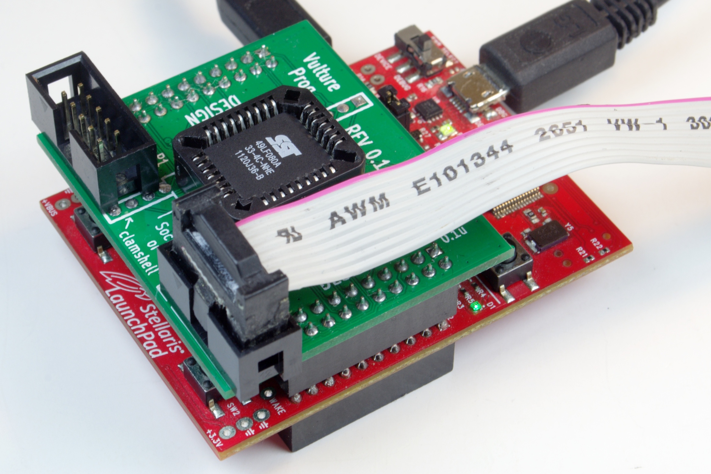
My focus for the remainder of this week will be to shorten this list as much as possible. Once the dependency between read and write is unshackled, I will be able to erase/program/verify my faithful SST 49LF080A. From here, it will be a matter of finalizing and implementing the last obscure bits of the specification.
The state of QiProg for flashrom
As QiProg is still being finalized, implementing it as a flashrom programmer is still a long ways ahead. I do estimate that weeks 11 and 12 will provide ample time to integrate everything into flashrom, hopefully, in time for the 0.9.8 release.