2015-08-14 Librem 13: Weekly Progress Update

A question coreboot developers are commonly asked is this: “can you port coreboot to my board?”

For my first coreboot post I’d like to show some of the steps required to port coreboot to the Librem 13. In particular, this post is a good example of some of the challenges involved in such a port.

This post is also the first weekly progress update for the Librem 13. Please email me with questions or comments: larry.moberg@puri.sm.

LPC Bus

The Librem 13 has convenient test points for the LPC bus. This allows a bed-of-nails test setup to quickly diagnose problems during manufacturing. But it has the added bonus of facilitating coreboot development.

The earliest coreboot stages are the most important to get right. Debugging using port 0x80 writes on the Librem 13 is possible because port 0x80 writes are configured as LPC writes, which can be traced by connecting to the LPC pins.

And…It’s Gone

BIOS development is hard. I applied a little too much force on the SPI flash chip and tore the solder pads off the board.
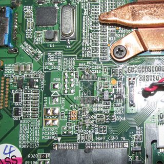
Pads...gone

I attached the LPC connection to a test setup and didn’t check using a multimeter before applying power. LAD2 was shorted to LAD3. This immediately bricked the laptop without even releasing any smoke. Remembering to double check for shorts is a tedious but important lesson.
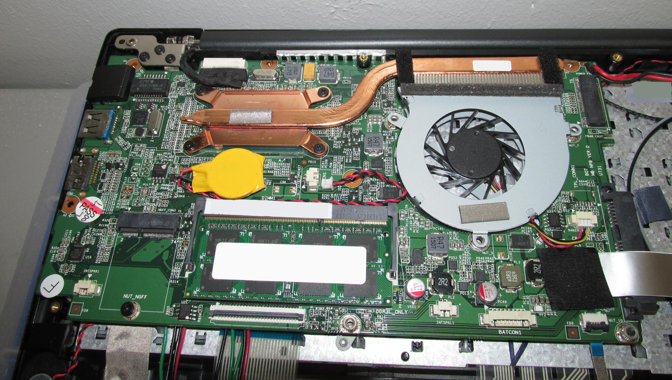
Don't Cross The Streams

The LPC bus wires go under the board. Don’t Cross The Streams!

Why It Matters

Imagine a laptop where the LPC bus is only available by soldering directly to the pins of the EC. Yes, they exist! That level of fine soldering is a significant barrier for future coreboot hackers. (The Librem 13’s external USB ports are all USB 3, which makes an EHCI debug port harder, but the LPC bus is a good substitute.)

Porting coreboot to a new laptop takes a lot of time and work. Even a good laptop design like the Librem 13 where the LPC pads are available still has a non-trivial level of engineering work to get to a Free Software BIOS.

Next week, I’ll document the engineering considerations around writing to the SPI flash chip, and how that affects coreboot development.

GSoC 2014 Projects

Congratulations coreboot’s GSoC students.  coreboot has three students working on coreboot for GSoC 2014 .


Title: Enhance early coreboot debugging

Student: Kyösti Mälkki

Mentors: Martin Roth and Rudolf Marek


Title: Generic Interface using alternate CBFS access patterns for ARM SoCs

Student: Naman Govil

Mentors Aaron Durbin and Marc Jones


Title: The yearly flashrom maintenance and enhancement proposal

Student: Stefan Tauner

Mentors Carl-Daniel Hailfinger and David Hendricks


Each student is required to post progress to this blog.  We expect first posts later this week. Stay tuned for progress!

GSoC 2011: midterm report under panic

Well my progress is not so shiny as other students. Looks like I overestimated my capabilities in my project proposal. I ended up with long exam session, lurking by reading coreboot mailing list (like an old cow), reading stuff about computer architecture, making hardware tools and trying to understand how git works 🙂

Done some patches, unfortunately, nobody likes it 🙂

Temporary libpayload fixes for flashrom as a payload

Flashrom as a payload with usb flash drive support

SerialICE for coreboot

Triggering another payload

For the second half of GSoC:

I’m working on “carFlashrom” (Yep, sounds a bit french) project:

http://www.coreboot.org/pipermail/coreboot/2011-July/065902.html

If this project is possible, then flashing would be possible without working RAM.

I would like to receive some response to my mails in the list as I am confused with my project goals, what others do think? I need some alternative goal if this is not feasible.

Give me some thoughts.


Bonus for readers: this one might be used with flashrom as rayer_spi. Modify flashrom source according to pinout and bits of par port registers:

http://logix4u.net/Legacy_Ports/Parallel_Port/A_tutorial_on_Parallel_port_Interfacing.html

I used m74hc244 from ST, even though parport signals are 5V, the chip is working right with VCC 3.3V.

http://dev.frozeneskimo.com/resources/jtag_wiggler_clone

u-boot as coreboot payload

U-boot is bootloader on ARMs, PowerPCs and other platforms, it has a nice set of commands and in general it feels like a small operating system. I’m not certainly sure if it is good direction, please feel free to compare with UEFI 😉 but I simply miss it on x86. I work at SYSGO with u-boot in daily basis and even port it to different boards/platforms. The x86 is no easy to init and I think this is the reason why there is only one x86 board in whole u-boot tree. This board is called eNET and it has a AMD ELAN SC520 SOC. But luckily, with coreboot we can init much more x86 boards and this leads to natural conclusion to have the u-boot as the coreboot payload. I would like to share with you part of this “fantastic” hacking journey to make it happen. Continue reading u-boot as coreboot payload

A simple DLP-USB1232H based JTAG programmer with OpenOCD support

DLP-USB1232H and OpenOCD based JTAG adapter

Here's a quick introduction to using a cheap FTDI FT2232H based module (left-hand side on the photo) as a JTAG programmer together with the OpenOCD JTAG software for ARM and MIPS devices. The module I am using for thіs purpose is a DLP Design DLP-USB1232H, which is available from various sources (Digikey, Mouser, Saelig, and probably others) for 20-30 bucks plus shipping, depending on where you live.

By properly connecting the correct pins of the DLP-USB1232H to the target JTAG
device (I used an Olimex STM32-H103 eval board for testing) you can easily abuse the DLP-USB1232H as JTAG programmer. As I chose the proper DLP-USB1232H GPIOs for the TRST and (S)RST pins, OpenOCD even worked out of the box, without having to change a single line of code.

The only thing that's required is to provide OpenOCD with an interface config file that uses the usbjtag "layout". I have already submitted that config file upstream, I guess it should be merged soonish.

The usage is then pretty simple:

  $ openocd -f interface/dlp-usb1232h.cfg -f board/olimex_stm32_h103.cfg

And in another xterm:

  $ telnet localhost 4444
  > init
  > reset halt
  > flash write_image erase fancyblink.bin 0x08000000
  > reset

This flashes the given fancyblink.bin image onto the STM32-H103 eval board via the DLP-USB1232H JTAG programmer, where fancyblink.bin is an example program from my libopenstm32 project (that aims to create a full-blown firmware library for ST STM32 microcontrollers, similar to what avr-libc does for AVRs). Contributions for libopenstm32 (license is GPLv3 or later) are highly welcome btw., hint hint...

  $ git clone git://libopenstm32.git.sourceforge.net/gitroot/libopenstm32/libopenstm32

Full schematics, datasheets, and detailed instructions for the JTAG programmer are available from a small page I created in my Random Projects wiki, which is intended for the various smaller projects I'm working on that don't warrant getting their own domain, wiki, etc:

The Random Projects wiki is open-for-all btw, feel free to use it for any freeish, software or hardware projects of your own if you want.

Anyway, the DLP-USB1232H is a really nice device as it can also be used for many other purposes, such as USB-to-Serial or SPI BIOS chip programming, but more on that in another blog post...