GSoC 2011: midterm report under panic

Well my progress is not so shiny as other students. Looks like I overestimated my capabilities in my project proposal. I ended up with long exam session, lurking by reading coreboot mailing list (like an old cow), reading stuff about computer architecture, making hardware tools and trying to understand how git works 🙂

Done some patches, unfortunately, nobody likes it 🙂

Temporary libpayload fixes for flashrom as a payload

Flashrom as a payload with usb flash drive support

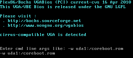
SerialICE for coreboot

Triggering another payload

For the second half of GSoC:

I’m working on “carFlashrom” (Yep, sounds a bit french) project:

http://www.coreboot.org/pipermail/coreboot/2011-July/065902.html

If this project is possible, then flashing would be possible without working RAM.

I would like to receive some response to my mails in the list as I am confused with my project goals, what others do think? I need some alternative goal if this is not feasible.

Give me some thoughts.


Bonus for readers: this one might be used with flashrom as rayer_spi. Modify flashrom source according to pinout and bits of par port registers:

http://logix4u.net/Legacy_Ports/Parallel_Port/A_tutorial_on_Parallel_port_Interfacing.html

I used m74hc244 from ST, even though parport signals are 5V, the chip is working right with VCC 3.3V.

http://dev.frozeneskimo.com/resources/jtag_wiggler_clone

GSoC 2011: flashrom + filo = ?


The answer is flashrom payload, which is capable flashing roms out of usb stick. If you use seabios, you will be able to choose to run this payload instead of booting os. It might be worth for payload developers if we would have a small payload for selecting other payloads out of CBFS 🙂

Patches are here. Sorry for weird stuff there 🙂


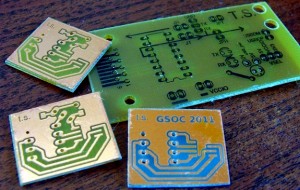
My GSOC project is not going well, I end up with problems almost everywhere 🙁 (Only the good thing is that my exams went well). I spend my time trying to understand what is going on. Yesterday I was running an overflowing code allmost all day, until I found out what is wrong… My E350M1 is still not working (coreboot doesn’t run with 512 kB chip). So I have ordered some chips from ebay. While I’m waiting I have made some PCB adapters to make a dual flash device. Also made additional PCB for RS232<->UART<->USB interface.

I would better go coding… Bye!

GSoC 2011: flashrom part 2 – SFDP

SFDP (Serial Flash Discoverable Parameters) is a JEDEC standard for querying the capabilities of serial flash chips. This allows software like flashrom to support chips without having all properties hard-coded beforehand. SFDP is structured in tables which are laid out in their own linear address space (independent from the “normal” range used to access the stored data). Starting at address 0x0 a mandatory header begins with a signature 0x50444653 (or ‘S’, ‘F’, ‘D’, ‘P’ in ASCII) followed by versioning data and the number of parameter headers. These headers are 64b long and have fields for versioning data, identification, length and offset where the real stuff i.e. the parameter table resides. There is one mandatory table and up to 255 can be added optionally. In the current version of the standard (2011-04) only the mandatory table is defined, but vendors are free (and quite encouraged by the standard) to add their customized tables and from the few data sheets i have seen mentioning SFDP the vendors do that (see below).

I spare you from the nasty details, but keep in mind that the mandatory table allows to retrieve the following properties:

  • the total size of the device
  • 4 (unified) block erasers (size of erase blocks and associated opcode)
  • address mode (24b, 32b or both)
  • status register write enable (none, WREN or EWSR)
  • lots of fast read-related stuff (like modes supported and number of wait states/dummy cycles needed in each)

The good news is: this would be enough to allow flashrom to work with unknown (yet unreleased) chips without recompilation!

The even better news is: i have a patch for that 😉

The bad news: i am not sure if there exists any hardware that supports it yet. Continue reading GSoC 2011: flashrom part 2 – SFDP

GSoC 2011: flashrom part 1 – Hardware Sequencing

Hey there!

My name is Stefan Tauner and I am the one GSoC student working on flashrom this summer. I live in Vienna/Austria where i am studying computer engineering since 2005 (almost done, I only need to find someone writing my thesis for me… should ask some politicians where they got their ghostwriters…).

Since I started playing around with flashrom and proposed my GSoC project in March I have been quite active in the small flashrom universe. The current main maintainers and contributers – Carl-Daniel Hailfinger, Stefan Reinauer and Michael Karcher – were all very busy and so i was drawn into handling the daily support with the help of other regulars (most outstandingly Idwer Vollering, thank you!). This proved to offer very good opportunities to dive into the code base to answer the questions of others and to get familiar with the overall design. It also led to numerous (mostly tiny) patches authored by me which can be viewed on our patchwork site.

Although I think this was all quite fruitful and also in the best interest of flashrom the main objective is something else: Add support to unlock flash regions on newer Intel chipsets. Many details can be read on the thread leading to my GSoC application here. In this post i will focus on a tiny related bit, that i have already implemented and is currently under review: Hardware Sequencing.

Two weeks ago I wrote a lengthy mail to our mailing list (which you certainly should follow if you are interested in our work!) about my plans to implement hardware sequencing for Intel chipsets and some related questions. You can read it at our mail archive site too, but i will republish it here almost in full (please forgive me the left out capitalization etc.). Continue reading GSoC 2011: flashrom part 1 – Hardware Sequencing

GSoC project: Coreboot panic room. Diagnostics (also remote flashing)

I’m very excited to announce my GSoC project which is intended to bring some light for coreboot users. To begin with, I would like to introduce myself. I’m 20 years old student living in Lithuania. I’m studying Informatics Engineering at Kaunas University of Technology. This year we have two interesting modules here: one about operating systems and the other is introduction to computer architecture, which is crucial for learning coreboot. Some time ago I have played with avr microcontrollers, so I have good soldering skills. One day during my free time I thought:

What the hell my old computer’s bios is so badly written that it can’t boot from usb flash and it can’t suspend correctly on Linux? I have a laptop that is running bios stuff more time than the old computer. I thought I can’t live with that and then I found coreboot 🙂 I was very excited that it was so configurable, so open alternative 🙂

Not to waste time on cheap talks, here is my project:

To help developing coreboot code, we have to set-up remote diagnostics (also flashing) interface in coreboot. We will be a able to renew bricked board through serial port or even do some research through registers in case of panic(). This will enable easier development of CAR, chipset, payloads code.

Abbreviations used later:
TARGET – machine running coreboot;
HOST – machine running serial port application, connected to TARGET through serial port
The platform that I will use for development is traditional x86. In case coreboot is supported on ARM, I will be hapy to buy one board to make my code working on both platforms.


There will be a diagnostics shell, similar to Serial ICE (or LLshell). Invocation of the shell may occur at any time (when we have (cache or ram) memory or not). It would be invoked by (we should discuss this):
1) serial port data received interrupt (HOST triggers diagnostics mode)
2) if user specified it in code (we may add something like checkpoints in coreboot’s code where TARGET will send command through serial port to HOST and if receives the answer – it enters diagnostics mode)
3) in case of panic() invocation (or something like die())


In that shell’s loop we will be able:
1) to run the code instructed through serial port (like Serial ICE): manage register contents, do some research or even like Carl-Daniel suggested to initialise CAR
2) to flash memory through serial port, when we have some memory (CAR or RAM) initialised. Some generic flashing code will be pumped through serial port to memory and then executed.


Some small specific goals:
1) analyse different code handling schemes in cases of memory we have (no memory, CAR, RAM)
2) define how Serial ICE will be integrated to coreboot
3) integrate defined Serial ICE stuff to coreboot as our new shell
4) add memory handling funcions to our new shell (for checking how much memory we have, and if we have – for uploading code to memory)
5) analyse flashing protocols
6) develop uniform flashing scheme (for SPI, parralel flash…) define what commands are required, where these commands should reside.
7) make serial port application for HOST (maybe we will use flashrom’s serprog code, it might require enhancing)


These are just milestones, some points may change after deeper investigation, when we will have something done.
We may experience the risk of problems in different operating modes when having different memory (no memory, CAR, RAM).


Yesterday I was looking at flashrom sources. People have done very good job in preparation for porting it to libpayload. Maybe I should concern making a complete flashrom port on libpayload?
Anyway, thanks for reading about my project. You are welcome to post some comments (maybe on the mailinglist). Your experience would be helpful.
Thanks to our mentors for their patience 🙂

FOSDEM 2011 photos

I just found out that nobody wrote a few lines about this year’s FOSDEM 2011. This year we had a booth (aka a “table”) in one of the buildings. We had total 4 speeches. I did one lightning talk about the coreboot and x86 init (video) and a lecture about coreboot and its speed. Carl-Daniel Hailfinger had lightning talk (video) and a talk about RAM Cold Boot Attacks The talks had a great success and a lot people attended. Continue reading FOSDEM 2011 photos

flashrom: Which hardware do you want supported?

flashrom is growing rapidly and we are constantly adding support for new SATA/PATA controllers, network cards, graphics cards, USB devices, JTAG cables, DIY hardware hacks, desktop/server mainboards and even some laptops.

If you own a piece of hardware which has a flash chip and lives in a PC (embedded devices with NAND flash are already covered by other software), and if you want to reflash that piece of hardware, please comment here (with some info on how to reach you) or mail us at flashrom@flashrom.org. We will use this to prioritize support for hardware people are interested in.

Continue reading flashrom: Which hardware do you want supported?

openbiosprog-spi, a DIY Open Hardware and Free Software USB-based SPI BIOS chip flasher using flashrom

openbiosprog-spi device

If you're following me on identi.ca you probably already know that I've been designing a small PCB for a USB-based SPI chip programmer named openbiosprog-spi.

The main use-case of the device is to help you recover easily from a failed BIOS upgrade (either due to using an incorrect BIOS image, due to power outages during the flashing progress, or whatever). The device only supports SPI chips, as used in recent mainboards (in DIP-8 form factor, or via manual wiring possibly also soldered-in SO-8 variants). It can identify, read, erase, or write the chips.

Of course the whole "toolchain" of software tools I used for creating the hardware is open-source, and the hardware itself (schematics and PCB layouts) are freely released under a Creative Commons license (i.e., it's an "Open Hardware" device). The user-space source code is part of flashrom (GPL, version 2), the schematics and PCB layouts are licensed under the CC-BY-SA 3.0 license and were created using the open-source Kicad EDA suite (GPL, version 2).

openbiosprog-spi schematics
openbiosprog-spi Kicad PCB layout

The schematics, PCB layouts, and other material is available from gitorious:

  $ git clone git://gitorious.org/openbiosprog/openbiosprog-spi.git

You can also download the final Gerber files (ZIP) for viewing them, or sending them to a PCB manufacturer.

Some more design notes:

  • The device uses the FTDI FT2232H chip as basis for USB as well as for handling the actual SPI protocol in hardware (MPSSE engine of the FT2232H).
  • Attaching the SPI chip:
    • There's a DIP-8 socket on the device so you can easily insert the SPI chip you want to read/erase/program.
    • Optionally, if you don't want a DIP-8 socket, you can solder in a pin-header with 8 pins, which allows you to connect the individual pins to the SPI chip via jumper wires or grippers/probes.
  • The PCB board dimensions are 44mm x 20mm, and it's a 2-layer board using mostly 0603 SMD components.

Basic usage example of the device on Linux (or other OSes supported by flashrom):

  $ flashrom -p ft2232_spi:type=2232H,port=A -r backup.bin (reads the current chip contents into a file)

openbiosprog-spi PCBs
openbiosprog-spi parts list

Over at the main projects page of openbiosprog-spi at

  http://randomprojects.org/wiki/Openbiosprog-spi

I have put up a lot more photos and information such as the bill of materials, the Kicad settings I used for creating the PCBs, the Gerber files and the Excellon drill files and so on.

The first few prototype boards I ordered at PCB-POOL.COM (but you can use any other PCB manufacturer of course), the bill of materials (BOM) lists the Mouser and CSD electronics part numbers and prices, but you can also buy the stuff elsewhere, of course (Digikey, Farnell, whatever).

I already hand-soldered one or two prototypes and tested the device. Both hardware and software worked fine basically, you just need a small one-liner patch to fix an issue in flashrom, but that should be merged upstream soonish.

In order to make it easy for interested users to get the PCBs I'll probably make them available in the BatchPCB Market Place soonish, so you can easily order them from there (you do still need to solder the components though). Note: I'm not making any money off of this, this is a pure hobby project.

All in all I have to say that this was a really fun little project, and a useful one too. This was my first hardware project using Kicad (I used gEDA/PCB, also an open-source EDA toolsuite, for another small project) and I must say it worked very nicely. I didn't even have to read any manual really, it was all pretty intuitive. Please consider not using Eagle (or other closed-source PCB software) for your next Open Hardware project, there are at least two viable open-source options (Kicad, gEDA/PCB) which both work just fine.

flashrom supports PowerPC and MIPS

You can now use flashrom on PowerPC and MIPS with most programmers. I added the last bit of infrastructure in version 0.9.2-r1111, and we got a few success reports since then. All USB/serial/network drivers work, and quite a few PCI drivers work fine as well.

Added bonus: If your flashrom driver selection does not need direct hardware access (e.g. USB programmers, serial programmers, dummy, …) you can now compile flashrom on all architectures, even those which are not explicitly supported. That feature was added in version 0.9.2-r1116.

This is a big step forward for flashrom which had been x86 centric since the beginning.

Continue reading flashrom supports PowerPC and MIPS